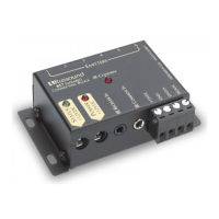
PRODUCT OVERVIEW
The 857 Connecting block connects IR receivers, power supply and emitters,
together to interface the IR system to the audio / video components.
KEY FEATURES
1) Six emitter output connections.
2) Convenient IR confirmation LED.
3) Status power receptacle with LED indicator.
4) Power receptacle with LED indicator.
5) Three conductor 1/8” receptacle for interfacing with many brands of
freestanding IR receivers.
6) Two conductor 1/8” receptacle for common IR input.
7) Large detachable IR receiver connection.
8) Compact size for mounting near audio equipment.
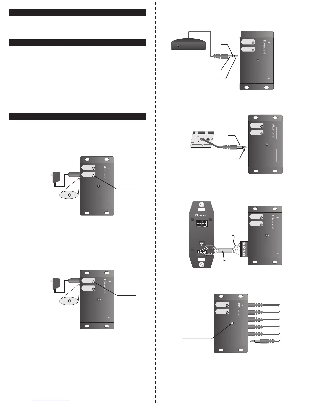
857 CONNECTIONS
Power: Connect a 12 VDC 200 mA to 1A power supply to the power jack.
2.1mm + Tip – sleeve. The red LED will be illuminated when powered. This
will power all of the IR components connected to the system. Depending on
the type of components and the number of components will determine how
much current the power supply will need to provide.
Status Power: 12VDC 200mA 2.1mm + tip –sleeve. Connecting a power sup-
ply to this connection will power the status connection. The green LED will
be illuminated when powered. This can be from a 12 volt trigger output or
from a wall type power supply plugged into a switched outlet of a stereo
receiver. If you are using products like the 858 that have a status indicator,
simply plug a 12 VDC power supply into the switched outlet and when the
receiver is turned on the status LED will be illuminated.
IR Receiver In: This is a three terminal 1/8” plug that is common to many of
the free standing IR receivers. This will connect the power, ground and sig-
nal. Signal is Tip, ground is the ring and power is the sleeve.
IR Common In: This is a two terminal 1/8” plug. Signal is tip, ground sleeve.
This can be connected the IR output of a stereo receiver or the common IR
output of an audio distribution system.
System Connection: Connect the IR system to the detachable connector
labled +12VDC, GND, STATUS and SIGNAL.
Emitter Outputs: Connect up to 6 emitters to the emitter jacks labeled 1-6.
Place the emitters on the source equipment.
IR Confirm: When an IR signal is received the IR confirmation blue LED will
flash.
Mounting: Mount the 857 near the source equipment that the emitters are
attached to.
 Loading...