EasyManua.ls Logo

Rutland ESM401 - User Manual

Rutland ESM401
16 pages
Print Icon
To Next Page IconTo Next Page
Loading...
Energiser Installation Guide
Thank you for purchasing a Rutland mains powered electric fence energiser.
We believe this unit is the best of its kind for ease of use, reliability and
durability. This guide provides instruction to properly install, operate and
maintain your unit, ensuring the most effective performance.
For Mains Powered Energisers
ESM401, ESM402,
ESM602, or ESM902
ESM1100, ESM2200,
ESM3300, or ESM4400
Question and Answer IconNeed help?

Do you have a question about the Rutland ESM401 and is the answer not in the manual?

Summary

Before You Start

Installation of Energiser and Fence

Guidelines for installing energisers and fences safely and correctly, including distance and warning sign requirements.

Manufacture Standard

Details on compliance with CE, IPX4, EN60355-2-76, EN55014 standards, and EMC.

Safety Precautions

Key safety measures for energiser use, including keeping away combustibles, indoor use, and cord safety.

Tools and Components

Lists required tools like cutters and screwdrivers, and components like lead-out cable and earth stakes.

Energiser Installation Steps

Step 1: Mount Energiser

Instructions for mounting the energiser indoors or in a waterproof enclosure using single or double screw methods.

Step 2: Connect Earth and Fence Terminals

Procedure for connecting lead-out cables to the EARTH (green) and FENCE (red) terminals.

Step 3: Connect Earth System

Guidance on connecting the earth system, including driving earth stakes and ensuring a sound earth connection.

Step 4: Connect Lead-Out Cable to Fence Line

Details on connecting the lead-out cable to poly wire, poly tape, or poly rope fence lines.

Step 5: Power Energiser

Instructions for powering the energiser by plugging it into the mains supply.

Energiser Operation

Operation for ESM401-ESM902 Models

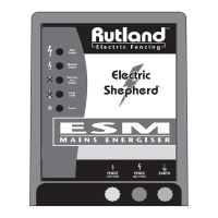
Explanation of pulse and power indicators, and the function of earth and fence terminals for specific models.

Operation for ESM1100-ESM4400 Models

Details on pulse indicators (high/medium output), warning/fault alarms, and fence terminal selection.

Maintenance and Testing

Fence Line Maintenance

Tips for maintaining the fence line, including regular voltage testing and keeping it clear of vegetation.

How To Test Fence

Procedure for testing the electric fence voltage using a tester.

How To Test Earthing

Procedure for testing the earthing system, checking voltage at the earth stake.

Energiser Troubleshooting

Troubleshooting Flowchart

Step-by-step guide to diagnose and resolve energiser issues based on voltage readings and common faults.

Warranty and Safety Information

Product Warranty

Details the two-year warranty, exclusions, and limitations of liability for manufacturing defects.

Limitation of Damages

Disclaims responsibility for consequential damages arising from product use or inherent risks.

WEEE Disposal

Instructions for the proper disposal of electrical equipment according to WEEE directive.

Overview

This document is an installation and user guide for Rutland mains-powered electric fence energisers, designed to provide instructions for proper installation, operation, and maintenance to ensure effective performance. The guide covers two main series of energisers: ESM401, ESM402, ESM602, ESM902, and ESM1100, ESM2200, ESM3300, ESM4400.

Function Description

Rutland electric fence energisers are designed to create an electric barrier for containing animals or deterring intruders. They convert mains electricity into high-voltage pulses that are sent along a fence line. When an animal or person touches the fence, they receive a short, harmless electric shock, which acts as a deterrent. The energisers are built to comply with CE, IPX4, EN60355-2-76 Health & Safety Standards, and EN55014 EMC, ensuring safety and reliability.

Installation Guidelines

The installation process begins with mounting the energiser. It is crucial to mount the unit in an indoor location or a waterproof enclosure to protect it from weather conditions, as mains energisers are for indoor use only unless certified for outdoor use with a minimum protection of IPX4. The guide illustrates both single and double screw mounting options.

Following mounting, the earth and fence terminals must be connected. Lead-out cables are used for these connections: one for the EARTH (green) terminal and another for the FENCE (red) terminal. The lead-out cable should be stripped approximately 4cm for connection.

A sound earth system is critical for the energiser's performance. The first earth stake should be driven beyond the drip-line of a building's eaves, at least 10 meters away from any domestic earthing system. Galvanized metal earth stakes, driven 1 meter (6 feet) deep, are recommended. If additional earth stakes are needed, they should be spaced 2 meters (6 feet) apart and connected with lead-out cable.

Connecting the lead-out cable to the fence line is the next step. The guide provides specific instructions and part numbers for connecting to poly wire (part no. 18-172), poly rope (part no. 30-125), and poly tape (part no. 30-158). It emphasizes ensuring all connection points, such as joiners and insulators, are sound and secure, as improper connections will negatively affect energiser performance.

Finally, the energiser is powered by plugging it into a mains power outlet. A warning is given that the energiser will immediately begin outputting voltage, and users should avoid touching the fence terminal or fence wire to prevent electric shock.

Safety Precautions

Several safety measures are highlighted throughout the manual:

  • Electric fences must be installed and operated to prevent danger to persons, animals, or surroundings, and should be out of reach of children and protected from mechanical damage.
  • Only one energiser should be connected to a single or multi-wire fence. Any other fence systems powered by a different energiser must be at least 2.5 meters apart.
  • Warning signs (yellow background, at least 100mm x 200mm, with "Caution Electric Fence" in black, 25mm high letters) must be placed at regular intervals along public roads or pathways.
  • Barbed wire must not be electrified.
  • Electric fences should not cross or run parallel to overhead power lines for great distances. If crossing is necessary, it should be at right angles, maintaining a vertical distance of at least two meters between the fence wire and the ground.
  • Maintain a distance of more than two meters from communication lines.
  • The electric fence earth must be more than 10 meters away from any domestic electricity board earth or telecommunications system earth.
  • Use insulated cable for connecting leads running inside buildings or underground, protecting them from damage. Do not install connecting leads in the same conduit as mains supply wiring, communication, or data cables.
  • Avoid touching electric fence wires, especially with the head, neck, or torso. Use gates or specially designed crossing points. Incorporate non-electrified gates or stiles where fences cross public pathways, with warning signs.
  • Keep combustible materials away from the energiser connection.
  • If the supply cord is damaged, it must be replaced by the manufacturer or a qualified person.

Usage Features

The energisers feature indicator lights for monitoring operation:

For ESM401, ESM402, ESM602, ESM902:

  • Pulse indicator: Flashes to indicate voltage output.
  • Power indicator: Flashes to show the energiser has power.
  • Earth terminal (green): Connects to the earth stake.
  • Fence terminal (red): Connects to the fence line.

For ESM1100, ESM2200, ESM3300, ESM4400:

These models offer more detailed feedback through multiple indicators:

  • Pulse indicator-high output: Flashes if output is over 5,000 volts.
  • Pulse indicator-medium output: Flashes if output is over 3,000 volts.
  • Warning low output: Flashes and an alarm sounds if output drops below 3,000 volts.
  • Earth fault alarm: Flashes if over 900 volts on earth, and an alarm sounds if over 1,100 volts on earth.
  • Power indicator: Continuous light shows the energiser has power.
  • Fence terminal low power (yellow): For short fences or paddocks.
  • Fence terminal high power (red): For long fences.
  • Earth terminal (green): Connects to the earth stake.
  • Both low and high power terminals can be used singly or simultaneously, and multiple lead-out cables can be attached to each terminal.

Maintenance Features

Fence Line Maintenance:

  • Regularly test voltage at the furthest point on the fence line from the energiser. Rutland Digital Tester 14-172 or 8-Light Tester 14-173 are recommended.
  • Routinely check all fence and earth connections for soundness.
  • Keep the fence line free of vegetation for best performance.
  • Keep insulators free from dirt, dust, and cobwebs.

How to Test Fence:

  1. Push an earth probe into the ground.
  2. Touch the fence contacts to the fence wire (for poly tape, insert between contacts and rotate 1/4 turn).
  3. The voltage will be displayed while maintaining contact with the fence line.

How to Test Earthing:

  1. Short the fence using a metal bar or wire approximately 100 meters along the fence.
  2. Push a probe into the ground near the earth stake.
  3. Touch the earth stake with a tester. If the reading is over 400 volts, the earthing is inadequate, and additional earth stakes (2 meters apart, connected by lead-out cable) are needed.

Energiser Troubleshooting:

The guide provides a comprehensive flowchart for troubleshooting common issues:

  • Daily check: Check voltage at the furthest point on the fence using a fence line tester.
  • Good voltage (over 3,000 volts): Fence line is O.K.
  • Less than 3,000 volts:
    • Check power supply for flat battery or electric supply off. Renew battery or contact an electrician.
    • If power is O.K., disconnect the fence line live output wire from the energiser and check voltage output across live and earth terminals with a tester.
      • If output is less than 3,000 volts, there is an energiser fault; contact Rutland for assistance.
      • If output is normal (over 6,000 volts), reconnect the fence wire.
  • Test earth stake: Short the fence line to the ground with an iron bar approximately 100 meters along the fence until the voltage reading is below 3,000 volts. If the earth stake(s) are effective, there should be below 400 volts reading on the earth stake. If higher, additional or deeper earth stakes are needed. Earthing can change with ground and climatic conditions.
  • Lead-out cable check (if earthing is O.K.): Disconnect the lead-out cable where it connects to the fence line and test the voltage at the cable end with a fence tester.
    • Under 5,000 volts: Lead-out cable is leaking to ground. Check if it's a specific lead-out cable, renew, and recheck.
    • Over 5,000 volts: Reconnect the lead-out cable to the fence line.
  • Common causes of low voltage/leaks:
    • Poor connection of lead-out cable to fence line.
    • Poor links between lines.
    • Metal object touching fence line.
    • Poor fence line joint or conductors.
    • Bad or incorrect insulator.
    • Fence line short or leak to ground.
    • Fence line touching a metal or soft wood post.
    • Very heavy vegetation against the fence line.
    • Leaking under gate cable under gateway.
    • Faulty underground cable at gateways.

A helpline is provided for further assistance if problems cannot be resolved.

Warranty and Disposal

The energiser comes with a two-year warranty against manufacturing defects, requiring proof of purchase. The warranty does not cover defects caused by improper installation, misuse, tampering, neglect, moisture, or other non-material/workmanship related reasons. The warranty is non-transferable and limited to repair or replacement.

The manual also includes information on WEEE (Waste Electrical & Electronic Equipment directive) compliance, advising users not to dispose of electrical products with normal household waste. Instead, they should return it to the retailer or take it to an authorized recycling center.

Rutland ESM401 Specifications

General IconGeneral
Power Rating400W
Dimensions215 x 115 x 50 mm
Operating Temperature-10°C to +50°C
Weight1.5 kg
ProtectionOver Voltage, Short Circuit

Related product manuals