5
Follow these steps to remove the attachment from the
upper shaft.
1. Loosen the knob by turning it counterclockwise.
2. Push the button while pulling out the attachment.
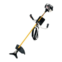
1. Place the bike handle bar (item 42) in the bottom
clamp (item 19) located on the shaft (item 8) housing.
The throttle trigger (item 9) must be mounted to the
operator's right side.
2. Insert the square tab of top clamp (item 43) into the
mounting hole of the bottom clamp.
3. Adjust the handle bar for best operator control in a
comfortable upright position.
4. Install the knob (item 44) and tighten securely.
1. Attach the blade guard (item 5) to the guard mounting
bracket (item 46); install the four screws (10-24 x 3/4in)
- (Item 45) from the top of the mounting clamp through
the blade guard and into the threaded mounting plates
(item 47).
2. Using the Torx wrench supplied, tighten all four screws
securely.
When using the line trimming head, the grass
deector (item 14) must be attached to the blade guard
(item 5).
1. Carefully align the locking tabs on the grass deector
(item 49) with the the slots on the blade guard (item
48).
2. Push the grass deector towards the blade guard until
the locking tabs click rmly into place.
The grass deector is tted with a line cut off blade.
Take extra care when tting the grass deector to avoid
contact with the sharp blade.
1. Stop the engine and disconnect the spark plug wire.
2. Remove currently installed line trimmer head or cutting
blade.
3. Open the Reel Easy Line Trimmer Head by depressing
the latches on each side. The contents of the line
trimmer head are spring loaded, so keep your
other hand over the line trimmer head cover while
depressing the latches. (image 3)
4. Remove the line trimmer head cover, bump knob, and
line spool and set aside.
49. Locking tabs
1. Starter grip
9. Throttle trigger
10. Trigger handle
11. On/Off switch
12. Throttle lock out button
50. Primer bulb
54. Throttle lock on button
55. Foam handle
20. Foam air lter
21. Air lter cover
22. Cover securing knob
23. Spark plug boot
24. Spark plug
25. Spark arrestor
26. Bump head spring
27. Bump head securing bolt
28. Cutting head housing
29. Blade ange washer
30. Gearbox
31. Shaft locking pin
32. Socket wrench
33. Cupped washer
34. Blade nut
35. Blade
36. Spanner
37. Gear shaft
38. Bump head cover
39. Bump knob
40. Line spool
41. Drive shaft adaptor
Follow these steps to connect the attachment to the upper
shaft (item 8).
1. Loosen the knob (item 16) by turning it counter
clockwise.
2. Align the button (item 18) on the attachment shaft with
the guide recess (item 51) on the upper shaft.
3. Slide the attachment shaft into the upper shaft until the
attachment shaft clicks into place.
4. Tighten the knob securely by turning it clockwise.