ASSEMBLY
10
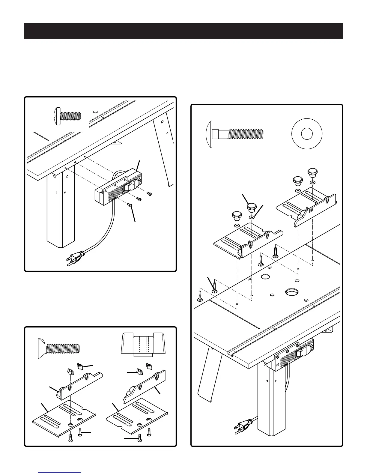
Fig. 3
TO ATTACH THE SWITCH BOX
See Figure 3
3. Place the router table on its legs.
4. Use a #2 Phillips screwdriver to attach switch box (P) to
the switch box bracket with 3 self tapping screws (U).
U (3)
P
U
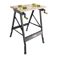
TO ATTACH THE FENCES
See Figure 4
5. Attach left fence (D) to left fence base (E) using 2 coun-
tersink screws (S) and 2 wing nuts (W). Repeat for right
fence (B) and right fence base (C).
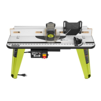
Fig. 4 Fig. 5
S (4)
W (4)
D
E
C
B
S
W
W
S
R (4)
V (4)
V
R
L
See Figure 5
6. Attach left fence assemblies to tabletop using 4 carriage
bolts (R), 4 washers (V) and 4 knobs (L). Make sure
that the turned down flange fits snug against inside wall
of provided groove in tabletop. Use a hammer to tap
carriage bolts (R) until seated to the bottom of the
tabletop.
Bdal 6144.461 3Sprachen 04.06.2005 11:56 Uhr Seite 10