18
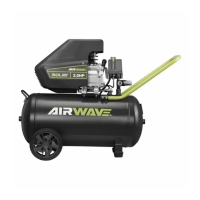
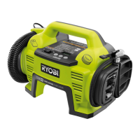
Fig. 12
A - Safety valve (soupape de sûreté, boquilla de la
seguridad)
B - Pull ring (tirer del anillo)
A
B
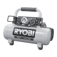
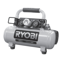
Fig. 11
D
A - Auto/off switch (l’interrupteur
fonctionnement automatique/arrêt, interruptor de
encendido/apagado)
B - Tank pressure gauge (manomètre de réservoir,
manómetro del tanque)
C - Regulatory pressure gauge (manomètre du
régulateur, regulador de presión manométrica)
D - Pressure regulator knob (bouton du régulateur de
pression, mando de regulación de presión)
C
A
B
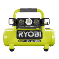
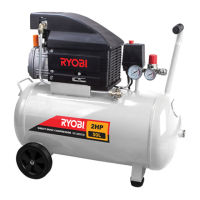
Fig. 13
A - Drain valve (soupape de vidange, válvula de drenaje)
A
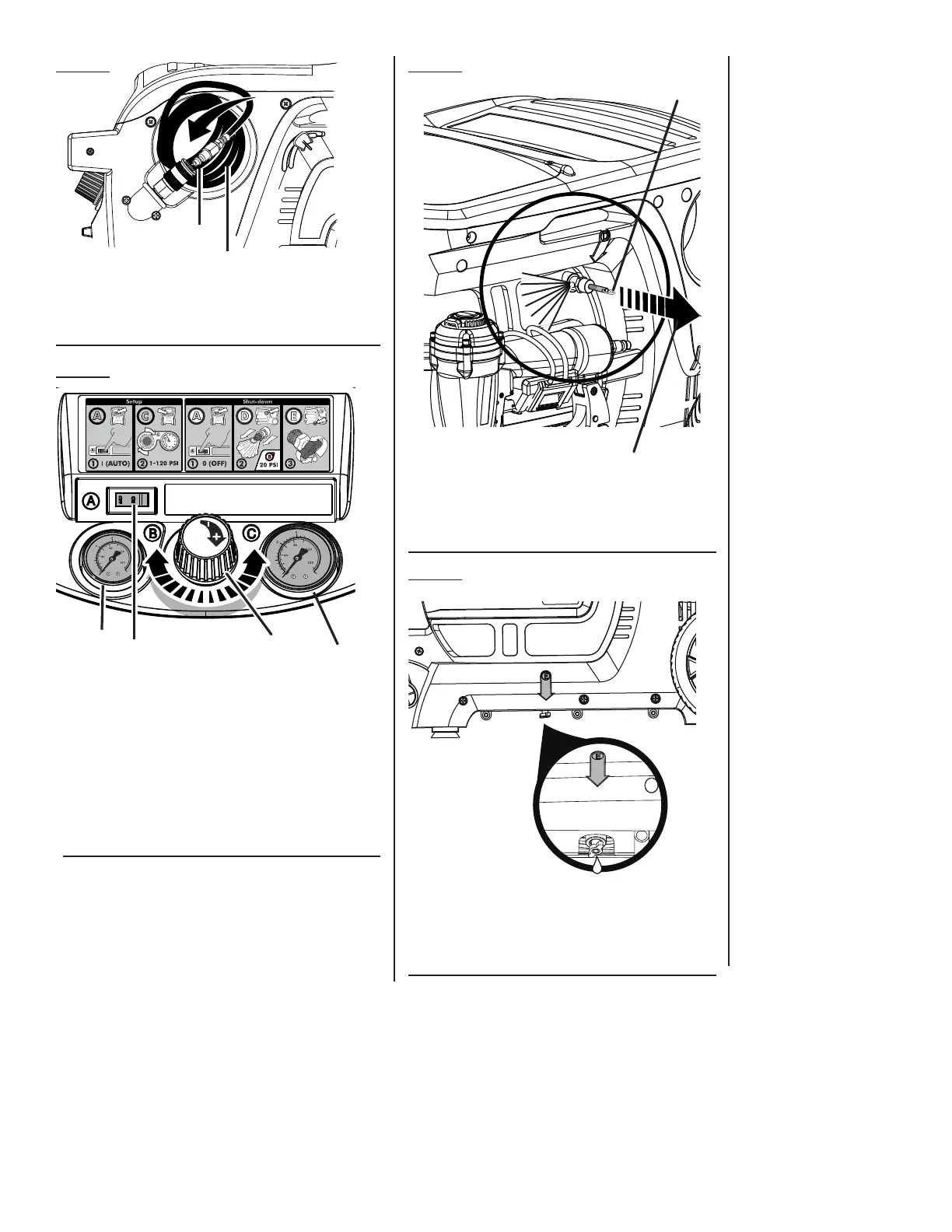
Fig. 10
A
B
A - Quick coupler (raccord rapide, acoplador rápido)
B - Coiled hose (flexible spirale, manguera de aire)