Do you have a question about the S.E.P. REV. 1000 Diesel (2+2) and is the answer not in the manual?
General advice to prevent danger from incorrect use of the machine.
Explains the warning symbol indicating potential injury or death.
Emphasizes prudence as the golden rule to prevent accidents.
States that only trained and authorized people should operate the tractor.
Advises reading all manuals before use, servicing, or refueling.
Stresses reading and following all machine decals and replacing damaged ones.
Advises against loose clothing and wearing appropriate footwear and trousers.
Ensure all safety devices are present and functional; do not interfere with them.
Provides instructions and warnings for safely starting the engine.
Always disengage control levers before starting the engine and keep feet clear of attachments.
Avoid running the engine indoors due to toxic carbon monoxide exhaust fumes.
Do not disable or use the tractor if the engine shut-off safety device is missing or defective.
Check and add motor oil to the air filter to the marked level before first use.
Know how to stop the engine in an emergency and be familiar with all controls.
Only allow responsible, trained individuals to operate the tractor.
Operate away from people and animals, being responsible for any damage or injury.
Never use the rotary tiller without its protective hood and guards.
Operate only in daylight or good lighting, at walking pace. Do not run.
Exercise caution on slopes, operate across slopes, and avoid steep inclines.
Never work on slopes steeper than 30 degrees.
Avoid prolonged operation on slopes steeper than 20° for proper gasoline engine lubrication.
Do not operate if any hoods or safety devices are missing or defective.
Keep hands and feet away from all attachments during operation.
Never lift or transport the tractor with the engine running.
Inspect the ground and clear it of stones, wood, wires, and other foreign objects before starting.
Verify the PTO-coupled attachment operates correctly before starting the engine.
Never use PTO attachments near children or animals.
Keep hands and feet clear of the PTO-coupled attachment.
Ensure the reverse speed safety device is set correctly for front-mounted attachments, not when the tiller rotates.
Handlebars rotate 180° for front attachments, reversing gear and PTO lever functions.
Manufacturer is not responsible for damage from improper use of safety devices.
Stop engine and disconnect spark plug lead before any checks or repairs.
Investigate and address excessive vibrations immediately after stopping the engine.
Always stop the engine before adjusting any attachments.
Periodically check and ensure all nuts and bolts are securely tightened.
Do not store the tractor with fuel in a closed area due to flammable vapor risks.
Keep the tractor clean, as grass and oil residues are a fire hazard.
Handle fuel safely: store in designated containers, refuel outdoors, and do not smoke.
Complete refuelling before starting, avoid refueling when hot. Clean spills before starting.
Replace the exhaust pipe if it is worn or damaged.
The tractor serial number is stamped on the engine side of the gearbox.
Refer to the engine's Operation and Maintenance Manual for engine identification.
The tractor is marked EC in compliance with EU directives and amendments.
Details the type of marking for the two-wheel tractor 1000 (2+2) models.
Specifies test conditions: PTO disengaged, stationary on a concrete surface.
Specifies test conditions: PTO engaged, stationary on a concrete surface with elastic layer.
Details the type of marking for the two-wheel tractor 1000 (2+2) E model.
Specifies test conditions for 1000 E: PTO disengaged, stationary on concrete.
Specifies test conditions for 1000 E: PTO engaged, stationary on concrete with elastic layer.
Details the type of marking for the two-wheel tractor 1000 (3+2) models.
Specifies test conditions for 3+2: 85% RPM, PTO disengaged, stationary on concrete.
Specifies test conditions for 3+2: PTO engaged, stationary on concrete with elastic layer.
Lists available engine models (HONDA, ROBIN, LOMBARDINI, YANMAR) with specifications.
Standard rewind start device; electric starter available upon request.
Electric starter with key control uses a 12V battery with 28 Ah capacity.
Features a multi-plate dry clutch with a control lever on the left handlebar.
Speeds are engaged via a lever on the steering column.
Tractor has 2 forward and 1 reverse speed; 2 forward and 2 reverse with front attachments.
Tractor has 3 forward and 1 reverse speed; 2 forward and 2 reverse with front attachments.
Provides maximum speed data in km/h for different models and tire sizes.
Features a mechanical oil bath gear box.
Can be actuated by a lever on the left handlebar for locking/unlocking.
Independent, single-speed PTO driven by a control lever, max speed 943 rpm.
Uses a quick-change fitting for fast attachment installation and removal.
Adjustable in height and width; rotatable 180° for front attachments.
Mechanical, independent brakes on both wheels, operated by right handlebar levers.
Agricultural tread tires available in various sizes (4.00-8, 4.0-10, 16X6.50-8).
Wide range of easy-to-fit accessories available, including wheels, pumps, ploughs, and trailers.
Mass information is available on the identification plate installed on the machine.
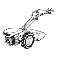
Overall dimensions of the two-wheel tractor are shown in figure 2.
Prevents reverse speed when PTO is rotating (two-wheel tractor only).
Stops the engine when handlebars are released (electrical or mechanical for Diesel).
A pin on the PTO control lever prevents concurrent reverse speed and attachment use (rotary tiller).
Pin pulled out: reverse speed engaged only after uncoupling PTO (two-wheel tractor).
Pin pushed in: reverse speed can be engaged with PTO operating (front-mounted attachments).
Mandatory to check safety pin position for the selected operating configuration (tractor or front-mount).
Displays various adhesive transfer printing decals for the basic machine operation and safety.
Shows decals related to the cutter bar attachment, including clutch release and tiller control.
Displays decals for the rotary tiller, including accident prevention and noise warnings.
Explains symbols used in the manual, such as workshop manual, safety distance, locked/unlocked.
Clutch lever operation: pulled up disengages, released engages. Engine stop lever: pressed down runs, released stops.
Differential lock for traction, PTO lever engages tiller drive. Functions may change with front attachments.
Handlebar vertical lock release for adjustment. 3rd speed preselection lever for special 3+2 versions.
Independent brake levers for cornering. Throttle lever controls engine speed from idle to max RPM.
Allows quick and easy coupling/decoupling of attachments to the PTO.
Details how to lock and unlock the differential for maximum traction.
Explains how to use the gear lever, including neutral and forward positions.
Details operation of the preselection lever for 3rd speed engagement in Special 3+2 versions.
Explains how to engage and disengage the PTO drive for the rotary tiller.
A safety device prevents reverse speed engagement when the PTO is operating with a rotary tiller.
Lever allows vertical adjustment of handlebars for operator comfort and tilling depth.
Lever controls engine speed, from idle to maximum RPM.
Independent brake levers for cornering and combined use for straight-line braking.
To lock wheels for parking, pull up both brake levers and engage brake locks.
Releases handlebar lock to rotate them for front-mounted attachments.
Lever has locked and released positions for securing the PTO adaptor.
Explains how gear and PTO levers reverse function when using front-mounted attachments.
Check and add motor oil to the air filter if fitted, before first use.
Ensure all control levers are disengaged before starting the engine.
Details steps for starting gasoline engines, including hood opening and fuel cock.
Press the engine stop lever to prepare for starting.
Pull the clutch lever fully up to disengage the clutch.
Lock the clutch lever using the provided locking device after engagement.
Turn the throttle control lever by 1/4 turn before starting the engine.
For gasoline engines, grip and pull the rope handle firmly and quickly to start.
For diesel engines, manually wind the rope and pull firmly and quickly.
Set throttle to idle and allow the engine to warm up after starting.
Move the throttle control lever to the idle position to stop the engine.
Release the engine stop lever to stop the engine.
For long-term storage of gasoline models, shut off the fuel cock.
Drain the carburettor bowl for gasoline models stored for over a week.
Before fitting, set safety device for 'motor mower' config, remove 3rd speed lever, reverse handlebars/wheels.
Verify control cable routing matches figure 16 for the two-wheel tractor version.
Position the reverse speed safety device correctly according to the direction of travel.
Check the locking pin is correctly positioned before use, especially for tiller operation.
Ensure correct preselection lever position before removal to avoid interference.
Handle the lever assembly carefully and store it safely for reinstallation.
Ensure control cables do not become tangled or caught while reversing the handlebars.
Ensure the PTO lever is in the 'disengaged' position before coupling attachments.
Push attachment shaft into PTO fully until it engages properly.
Lower the PTO lever to 'engaged' and verify the attachment is locked.
Instructions on how to adjust track width based on wheel type.
Wheels without adjustable rims (4.00-8) cannot have their track width modified.
Adjust track width on 4.00-10 wheels by positioning the flange inside or outside the rim.
Adjust 4.00-8 wheel track using pin holes and spacers, or by reversing wheels.
Adjust 4.00-10 wheel track using flange position, spacers, and wheel reversal.
Follow engine safety precautions and consult the engine manual.
Avoid heavy duty work during the first 50 hours and follow specific running-in instructions.
Clean dry air filter cartridge every 8 hours; replace if damaged.
Check oil level every 8 hours; clean filter element as per engine manual.
Filter cleaning frequency depends on operation, but should not exceed 8 hours.
Clean filter element and change filter oil as per engine manual.
Change gearbox/transmission oil after the first 50 hours of operation, preferably when hot.
Check gearbox oil level between maximum and minimum notches when cold.
Change gearbox and transmission oil every 300 hours following the running-in instructions.
Grease the PTO every 8 hours or every time a new attachment is fitted.
Adjust clutch lever free play (5-6mm) using the cable adjuster to prevent slip or non-disengagement.
Adjust cable using adjuster to ensure correct differential operation if lever movement is insufficient.
Adjust brake levers for 5-6mm free play using cable adjusters, ensuring uniform braking.
Do not use without hood, keep clear of tiller, stop engine before touching, ensure reverse safety device is correct.
Used for tilling gardens, orchards, vineyards; available in various widths (35-60 cm).
Details transmission, max rotation speed, working widths, and weights for different models.
Safety device prevents installation if machine is configured for front-mounted attachments (pin pushed in).
Release clutch lever gradually and sink tiller into soil slowly for smooth operation.
Model 1000E exclusively fits 50cm FIX tiller with a fixed 50cm bonnet.
Adjust working widths (40, 50, 60 cm) by reversing rotors or adding/removing tiller rotors.
Adjust protection guards by adding side extensions or using a matching piece with screws.
Adjust tilling depth by moving the tine up or down and securing with nut and bolt.
Adjust tiller height for hard ground (lower tine) or soft ground (lower tine for stability).
Check nuts and bolts are secure; change oil in the tiller drive unit.
Change the tiller drive unit oil every 300 hours as instructed.
Fit knife guard when transporting/finishing, keep clear of bar, stop engine before cleaning/adjusting, careful on slopes.
Reduce noise by not working at max RPM, keeping blade adjusted, and using ear protection.
Easily converts tractor to motor mower; ideal for mowing lawns, available in various sizes.
Release clutch gradually; do not release when load is applied to the mower.
Check and adjust play between wear plate and cutting knife using adjuster nuts/screws.
E.S.M. type S mowing bar does not require special adjustment as it is self-adjusting.
Adjust adjuster nut for each wear plate to obtain correct knife movement.
Adjust skids as necessary to set the required cutting height.
Regulate support slides until the blade is at the desired height.
Regulate support slides until the blade is at the desired height.
Turn adjuster screws to set required play between roller and push-rod.
Grease mower mechanism after first 5 hours and subsequently every 10 hours.