Do you have a question about the Sailor FleetBroadband 500 and is the answer not in the manual?
Legal notice disclaiming responsibility for use of product and documentation.
Lists registered trademarks of Thrane & Thrane, Microsoft, and Inmarsat.
Warning to avoid touching areas marked with a heat symbol to prevent injury.
Information on radiation levels and required minimum safety distances from the antenna.
Minimum safe distances to avoid radar interference and potential damage to the antenna.
Specifies minimum safe distances for compass proximity to terminal and antennas.
Rules regarding user access for service and precautions for internal adjustments.
Guidelines for grounding, power supply, and avoiding live circuits.
Defines the target audience and required skills for using the manual.
Guidance on how to obtain the latest version of the manual.
Describes the manual's structure, contents, and excluded topics.
Lists other documents relevant to the SAILOR 500/250 FleetBroadband systems.
Congratulatory message and introduction to the SAILOR FleetBroadband system.
Lists the key applications supported by the system, such as internet and email.
Details the system's capabilities, data speeds, and physical/logical interfaces.
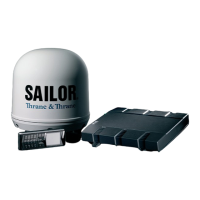
Describes the primary hardware components of the SAILOR 500/250 systems.
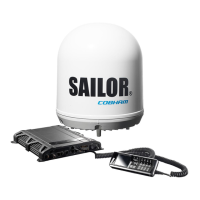
Details the antenna specific to the SAILOR 500 FleetBroadband model.
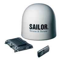
Details the antenna specific to the SAILOR 250 FleetBroadband model.
Describes the central terminal unit which controls the system.
The SAILOR 500/250 FleetBroadband system is a maritime broadband communication solution designed for vessels, providing simultaneous high-speed data and voice communication via satellite through the Broadband Global Area Network (BGAN). This system is available in two primary configurations: the SAILOR 500 FleetBroadband and the SAILOR 250 FleetBroadband, with the key distinction lying in their respective antenna units and the resulting bandwidth capabilities. Both systems also offer a 19" rack version of the terminal for integrated installations.
The core function of the SAILOR FleetBroadband system is to enable reliable and robust satellite communication for maritime applications. It facilitates a wide range of communication services, including internet browsing, email, phone and fax services, large file transfers, video conferencing, and streaming. Furthermore, it supports VPN (Virtual Private Network) access to corporate servers, allowing for secure and private data exchange.
The system operates on the BGAN network, providing full duplex communication for single or multi-user environments. The SAILOR 500 FleetBroadband offers higher data speeds, up to 432 kbps, while the SAILOR 250 FleetBroadband provides speeds up to 284 kbps. Both systems support streaming IP at various rates, with the SAILOR 500 offering up to 256 kbps and the SAILOR 250 up to 128 kbps. The SAILOR 500 FleetBroadband also uniquely supports ISDN (Integrated Services Digital Network) service at 64 kbps, which can be used for ISDN phones, G4 fax, or ISDN modems. Voice communication is supported through Standard Voice (4 kbps) or 3.1 kHz Audio.
The system comprises two main units: the antenna and the terminal. The antenna is responsible for tracking satellites and establishing the satellite link. The SAILOR 500 FleetBroadband utilizes the TT-3052A/B antenna, a maritime 3-axis controlled BGAN Class 8 antenna, which includes a built-in GPS for satellite tracking. The SAILOR 250 FleetBroadband uses the TT-3050A antenna, a medium-sized maritime 2-axis stabilized BGAN Class 9 antenna. A single coaxial cable connects the antenna to the terminal, carrying RF communication, supply voltage, and modem communication.
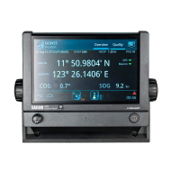
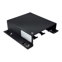
The terminal, either the TT-3738A SAILOR FleetBroadband Terminal or the TT-3738A-T19 SAILOR FleetBroadband 19" Rack Terminal, serves as the controlling unit for the entire system. It houses all user interfaces, LED indicators, and stores configuration data. It acts as a central hub, managing connections to various devices on board the vessel.
The SAILOR FleetBroadband system is designed for ease of use, offering multiple interfaces for connectivity and management. It features four LAN (Local Area Network) ports with Power over Ethernet (PoE), allowing direct connection of computers, e-hubs, and IP handsets without the need for separate power adapters. Additionally, it provides two Standard Phone/Fax ports for connecting conventional phones or fax machines. The SAILOR 500 FleetBroadband also includes a Euro ISDN port for specific ISDN devices. For maritime data broadcast reception, an L-Band output is available. A multi-purpose I/O connector with five configurable inputs/outputs offers flexibility for integrating with other ship systems.
The system incorporates a built-in DHCP/NAT router, simplifying network setup and management for connected devices. A crucial component for operation is the SIM slot, where the user inserts their BGAN SIM card to access the Inmarsat network.
A key user-friendly feature is the built-in web interface. This web-based platform allows users to manage their phone book, messages, and calls, as well as customize the terminal to their specific needs. The web interface provides access to various settings, including advanced setup of interfaces, and offers a dashboard for monitoring system status. It also facilitates software updates, selection of preferred BGAN satellites, and language settings.
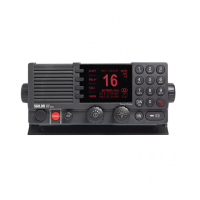
For direct interaction, the system includes a Thrane IP Handset & Cradle (TT-3670A). This IP handset functions as a standard phone but also serves as a user interface for the SAILOR FleetBroadband systems, allowing users to make calls, send messages, and access basic system functions.
The system's power supply operates within a voltage range of 10.5 - 32 V DC, making it suitable for typical marine electrical systems. It is recommended to connect it to the ship's 24 V DC bus.
While the SAILOR FleetBroadband system is designed for robust operation, certain maintenance aspects are outlined to ensure its longevity and proper functioning.
The manual emphasizes safety precautions, particularly regarding microwave radiation from the antenna during transmission. Users are advised to maintain a minimum safe distance from the antenna panel to prevent hazardous exposure. For the SAILOR 500, this distance is 1.3 meters (at 10 W/m²), and for the SAILOR 250, it is 0.6 meters (at 10 W/m²). Areas on the terminal or antenna that may become extremely hot are marked with a symbol, cautioning against touching them to avoid injury.
Regarding installation, the manual highlights the importance of maintaining a minimum safe distance between the antenna and radars to prevent damage. It also specifies compass safe distances for the terminal and both antenna types to avoid interference with navigation equipment.
User access to the interior of the terminal is strictly prohibited. Any service or internal adjustments must be performed by a technician authorized by Thrane & Thrane to avoid voiding the warranty. Access to the antenna's interior is permitted only for the replacement of specific modules, as detailed in the installation manual. It is crucial to always disconnect power and discharge circuits before touching them to prevent injuries, as dangerous voltages may persist even after power removal.
The system's cables are shielded to minimize interference from magnetic fields, but it is recommended to avoid running them parallel to AC wiring to prevent potential malfunctions. Proper grounding of the equipment chassis and cabinet to the ship's electrical ground is essential to minimize shock hazards.
For software maintenance, the web interface provides a function for uploading software updates, ensuring the system operates with the latest functionalities and improvements. The manual also includes a troubleshooting guide, status signaling information, event logging, and details about the Reset button, which can assist in diagnosing and resolving minor issues. In case of more complex problems, the web interface offers a help desk and diagnostic report feature, and users are directed to Thrane & Thrane's website for the most current manuals and support resources.
| Technology | Inmarsat FleetBroadband |
|---|---|
| Frequency Band | L-band |
| Data Rate (Downlink) | 432 kbps |
| Voice Channels | 1 |
| Voice Lines | 1 |
| Weight (Above Deck Unit) | 3.5 kg |
| IP Handset | Yes |
| Simultaneous Voice and Data | Yes |
| Power Supply | 10.5-32 V DC |
| Operating Temperature | -25°C to +55°C |
| Humidity | Up to 95% non-condensing |
| Category | Marine |
| Data Rate (Uplink) | 432 kbps |
| Antenna Type | Phased Array |
| Interfaces | Ethernet, Serial |
| Storage Temperature | -40°C to +80°C |