12
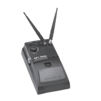
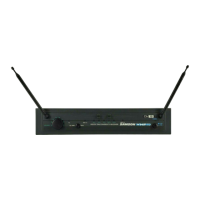
1. Antenna Jacks - The front BNC antenna jacks allow full rotation for optimum place-
ment. In normal operation, both antennas should be placed in a vertical position.
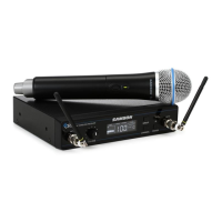
2. VOLUME Control - This knob sets the level of the audio signal being output through
both the balanced and unbalanced output jacks on the rear panel. Reference level
is obtained when the knob is turned fully clockwise (to its “10” setting).
3. LCD Display - Displays transmitter and receiver settings.
4. GROUP Button - Press and release button to cycle through the available groups. Press
and hold button to scan for available channels within the selected group.
5. CHANNEL Button - Press and release to cycle through available channels within a
group. Press and hold button to enter IR Set which is used to set the operating
channel of the transmitter.
6. POWER Button - Press and hold to turn the CR99 power on and off.
7. IR Transmitter - During “IR SET” an infrared light is used to set the transmitter
channel.
CR99 Receiver - Front Callouts
1 2 3
4
5 6
7
1

 Loading...