Do you have a question about the Samson ETM-3b and is the answer not in the manual?
Details power requirements, integrated circuits, transistors, diodes, and relays.
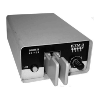
Covers dash-dot ratio, speed range, and SQUEEZE-keying with a double paddle.
Describes keyed line output, voltage/current limits, and the built-in sidetone.
Details the speed control with on/off switch and the tune key.
Provides the physical dimensions and net weight of the keyer.
Explains the power transformer voltage selection and electronic voltage stabilization.
Details oscillator, flip-flop stages, and transistor control for dot/dash generation and sidetone.
Explains conventional and SQUEEZE-keying, including character formation with paddle movements.
Instructions for removing the chassis and adjusting paddle gap and tension.
Describes the dry reed switch keying output and the protective 220 Ohm resistor.
Details power transformer operation, stabilized AC supply, and keyer timing circuits.
Explains SQUEEZE-keying advantages and paddle adjustment steps.
Discusses the dry reed switch, its snap action, and output current limiting.
Clarifies that the keying line is not electrically connected to the device's electronics or chassis.
Specifies max power, voltage, current, and required series resistors for transmitter keying.
Details sidetone impedance, speaker requirements, and battery connection for the amplifier.
Warns against using filtered Junker-type keys simultaneously with electronic keys.