EB 8484-1 EN 73
Optional additional functions
5. Keep hold of the rotary knob and tighten
the locking screw (3) (tightening torque
0.9±0.1Nm).
6. Move the valve away from the switching
position and check whether the output
signal changes.
7. Move the valve back to the switching po-
sition and check the switching point.
6.4.2 Adjusting the OPEN po-
sition
1. Initializethepositioner(seesection8.4).
2. Move the valve using the manual mode
(seesection8.5.7)to95%(readtheval-
ue off the display).
3. Undo the locking screw (3).
4. Turn the adjustment screws to adjust the
tagsuntiltheyleaveorentertheeld
causingtheswitchingampliertore-
spond. You can measure the switching
voltage for checking purposes.
5. Keep hold of the rotary knob and tighten
the locking screw (3) (tightening torque
0.9±0.1Nm).
6. Move the valve away from the switching
position and check whether the output
signal changes.
7. Move the valve back to the switching po-
sition and check the switching point.
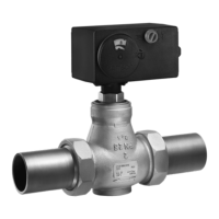
6.5 Turning the positioner shaft
To turn or hold the positioner shaft in posi-
tion, turn or hold the actual shaft lock by
hand.
Î Do not use the locking screw to turn the
positioner shaft knob. Only turn the
rotaryknobbyhand(seeFig.31).
Rotaryknob
Locking screw
Fig.31: Shaft lock

 Loading...