79
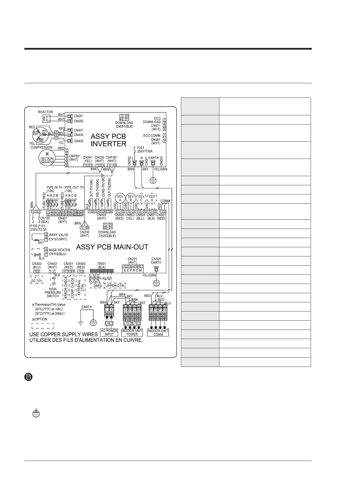
7. Electrical Wiring Diagram
7-1 Outdoor unit
2
AJ052/068TXJ3KG/EU, AJ080TXJ4KG/EU
ASSY PCB
INVERTER
Printed circuit board(Inverter PBA)
ASSY PCB MAIN Printed circuit board(Main PBA)
F001(250V/
T30A)
Fuse(Inverter PBA)
F100(250V/
T2.5A)
Fuse(Main PBA)
F101(250V/
T2.5A)
Fuse(Main PBA)
OUT-TH Thermistor(Ambient Temp. - 10kohm)
DIS-TH Thermistor(Discharge Temp. - 200kohm)
COND-TH Thermistor(Condensor Temp. - 10kohm)
OLP-TH
Thermistor(Compressor Top Temp. -
200kohm)
PIPE IN TH - A Thermistor(A Pipe In Temp. - 10kohm)
PIPE IN TH - B Thermistor(B Pipe In Temp. - 10kohm)
PIPE IN TH - C Thermistor(C Pipe In Temp. - 10kohm)
PIPE IN TH - D Thermistor(D Pipe In Temp. - 10kohm)
PIPE OUT TH - A Thermistor(A Pipe Out Temp. - 10kohm)
PIPE OUT TH - B Thermistor(B Pipe Out Temp. - 10kohm)
PIPE OUT TH - C Thermistor(C Pipe Out Temp. - 10kohm)
PIPE OUT TH - D Thermistor(D Pipe Out Temp. - 10kohm)
EEV - A Electronic Expansion Valve A
EEV - B Electronic Expansion Valve B
EEV - C Electronic Expansion Valve C
EEV - D Electronic Expansion Valve D
COMPRESSOR Motor(Compressor)
M-BLDC Motor(FAN)
4WAY VALVE Solenoid Valve(4Way)
BASE HEATER Heating Wire
NOTE
This wiring diagram applies only to the outdoor unit.
Colors BLK : black, BRN : brown, SKY-BLU : sky-blue, GRN/YEL : green/yellow, RED : red, YEL : yellow,
ORG : orange, BLU : blue, WHT: white
For connection wiring indoor-outdoor transmission, refer to the installation manual
Protective earth(screw)