81
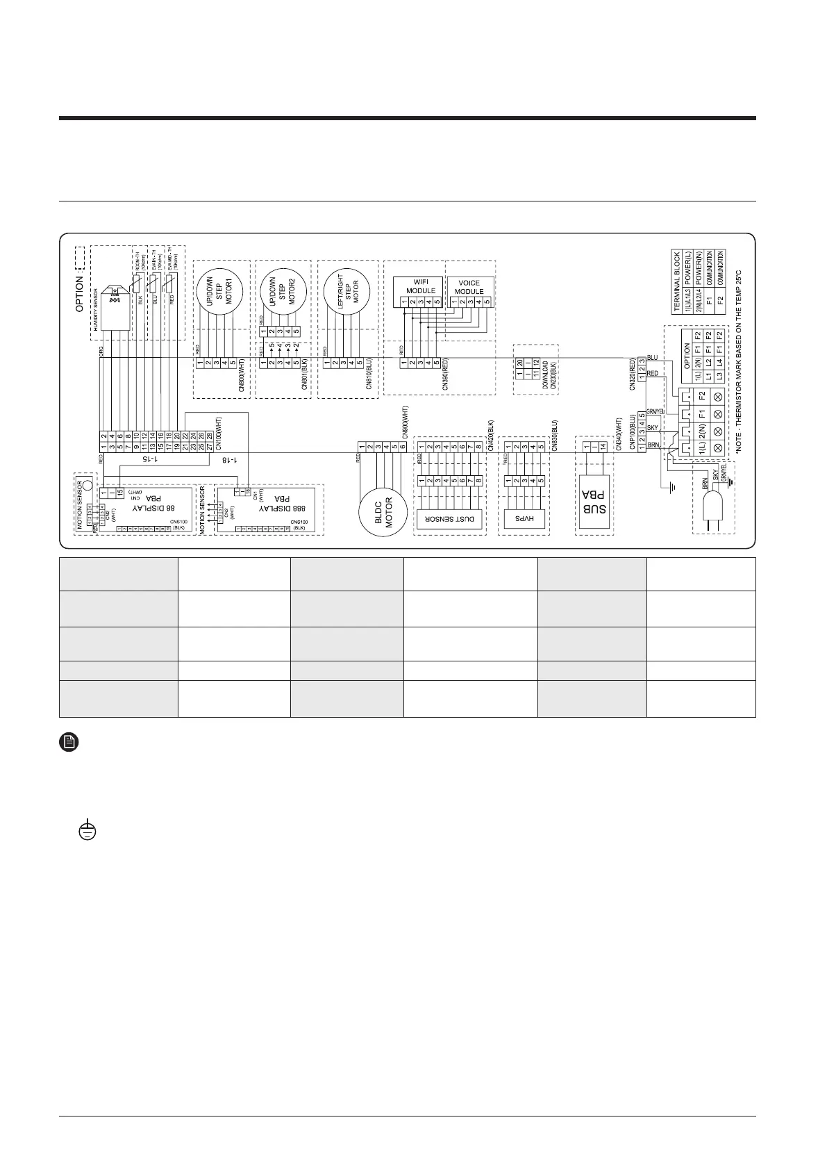
7. Electrical Wiring Diagram
7-2 Indoor unit
1
Wall-mounted : AR4500, AR5500, AR9500
MAIN PBA
Printed circuit
board(MAIN)
BLDC MOTOR BLDC Motor ROOM-TH(10K) Thermistor ROOM
88 DISPLAY
Printed circuit
board(DISPLAY)
HVPS
High voltage power
supply(Option)
EVA IN-TH(10K) Thermistor EVA IN
SUB
Printed circuit
board(SUB)
DUST SENSOR Dust Sensor(Option) EVA MID-TH(10K) Thermistor EVA OUT
WIFI MODULE Wifi(Option) HUMIDITY SENSOR Humidity Sensor(Option) STEP MOTOR1 Up/Down Louver
VOICE MODULE
Voice
recognition(Option)
STEP MOTOR Left/Rigth Louver STEP MOTOR2
Up/Down
Louver(Option)
NOTE
This wiring diagram applies only to the outdoor unit.
Colors BLK : black, BRN : brown, SKY-BLU : sky-blue, GRN/YEL : green/yellow, RED : red, YEL : yellow,
ORG : orange, BLU : blue, WHT: white
For connection wiring indoor-outdoor transmission 3(C), refer to the installation manual
Protective earth(screw)