84
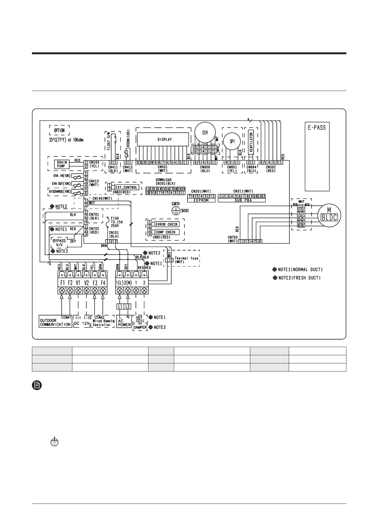
7. Electrical Wiring Diagram
7-2 Indoor unit
4 Home duct : AJ026TNLDEG/EU, AJ035TNLDEG/EU, AJ026TNLPEG/EU, AJ035TNLPEG/EU
MAIN PCB Printed circuit board(MAIN) M-BLDC BLDC Motor ROOM-TH(10K) Thermistor ROOM
DISPLAY PCB Printed circuit board(Display_Option) EEV Electronic Expansion Valve(Option) EVA IN-TH(10K) Thermistor EVA IN
FLOAT SWITCH SPI S-Plasma ion(Option) EVA OUT-TH(10K) Thermistor EVA OUT
NOTE
This wiring diagram applies only to the indoor unit.
Colors BLK : black, BRN : brown, SKY-BLU : sky-blue, GRN/YEL : green/yellow, RED : red, YEL : yellow,
ORG : orange, BLU : blue, WHT:white
For connection wiring indoor-outdoor transmission F1-F2, indoor-wired remotecontroller transmission F3-F4, refer to the
installation manual
Protective earth(screw)