3-1-1 Main Body Disassembly
1. Remove 1 screws on the bottom center of the
Rear Cover.
2. Remove signal connector from the shield.
3. Remove Rear Cover from the Front Cover.
4. Remove 4 screws on the Shield and remove
the shield.
5. Disconnect Inverter wire, Function PCB wire
and Interface wire.
Remove 4 screws on the Main PCB
6. Remove 2 screws on the Inverter PCB.
7. Remove the Main PCB Assembly.
8. Remove 3 screws on the Function PCB.
3-2-1 Removing the Stand
1. Remove 4 screws in the hinge area.
2. Disconnect DVI Cable and Signal Cable
and Power cord.
3. Pry it off the back of the monitor.
3-2-2 Main Body Disassembly
1. Face the monitor down on a soft-cushionea
flat surface.
2. Put the jig into the opening hole of the bottom.
3. Open the rear cover partly by pushing the jig
into left and right hole.
4. Put the jig into the opening hole of the top-
center and take the rear cover apart by
pushing it upward.
5. Remove 2 screws on the Inverter PCB.
6. Remove the Main PCB Assembly.
7. Remove 3 screws on the Function PCB from
locking area of Function knob and remove
Function PCB.
GH17P*/GH18P* 3-1
3 Disassembly and Reassembly
This section of the service manual describes the disassembly and reassembly procedures for the
GH17P*/GH18P* monitors.
WARNING: This monitor contains electrostatically sensitive devices. Use caution when handling
these components.
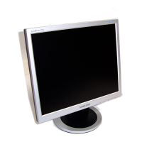
3-1 Disassembly (GH17P*)
Cautions:1. Disconnect the monitor from the power source before disassembly.
2. Follow these directions carefully; never use metal instruments to pry apart the cabinet.
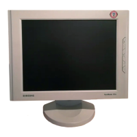
3-2 Disassembly (GH18P*)
Cautions:1. Disconnect the monitor from the power source before disassembly.
2. Follow these directions carefully; never use metal instruments to pry apart the cabinet.
 Loading...