Do you have a question about the Samsung LA32B650T1R and is the answer not in the manual?
Step-by-step instructions for disassembling and reassembling the LCD TV.
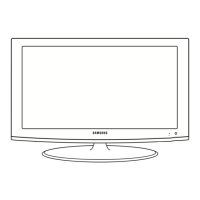
Visual breakdown of the LA32B650T1R model components.
Detailed list of parts for the LA32B650T1R model with codes.
Essential safety guidelines for handling, servicing, and installing the TV.
Procedures and precautions for servicing the LCD TV safely.
Procedures to prevent damage from static electricity to sensitive components.
Safety measures to follow during product installation and setup.
Comprehensive details on the TV's features, technical specifications, and performance.
Explanation of the Frame Rate Conversion and Motion Judder Cancellation technology.
Details on accessing internet content and display modes like Overlay and Viewport.
Description of video display modes.
Description of video display modes.
Description of built-in content.
Description of managing and downloading content via USB or TV memory.
Guide to viewing photos, listening to audio, and playing movies from USB devices.
Description of network connectivity.
Comparison of specifications between current and older TV models.
List of included accessories with their part numbers.
General guidelines and common issues for troubleshooting the TV.
Diagnostic steps for issues where the TV does not power on.
Troubleshooting steps for no video when using an analog PC signal.
Troubleshooting steps for no video when using HDMI input signals.
Troubleshooting steps for no video when using the Tuner or CVBS input.
Troubleshooting steps for no video when using the CVBS input.
Troubleshooting steps for no video when using Component input.
Diagnostic steps for audio issues when video is present.
Procedures for general alignment and adjustments of TV settings.
Instructions for accessing and using factory mode settings.
Steps for calibrating white balance for optimal color accuracy.
Adjusting white ratio for different input sources in factory mode.
Information regarding firmware updates via USB download.
Process for updating the sub-micom firmware using a JIG.
Internal wiring diagram for 32-inch and 40-inch models.
Internal wiring diagram for 46-inch and 55-inch models.
Explains the function of various internal connectors on the boards.
Identifies specific cables used for connections between boards.
| Screen Size | 32 inches |
|---|---|
| Resolution | 1920 x 1080 pixels |
| Display Type | LCD |
| Backlight Type | CCFL |
| Response Time | 4 ms |
| HDMI Ports | 4 |
| USB Ports | 2 |
| Audio Output | 10W x 2 |
| Aspect Ratio | 16:9 |
| Refresh Rate | 100 Hz |
| Brightness | 500 cd/m² |
| Speakers | 2 x 10W |
| Power Consumption | 120 W |
| Contrast Ratio | 50000:1 |
| Viewing Angle | 178° |




 Loading...