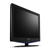
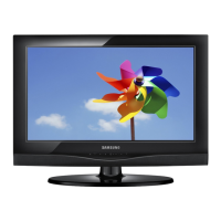
Do you have a question about the Samsung LE26B450C4H and is the answer not in the manual?
Diagram illustrating the signal flow for PC input.
Diagram showing the signal path for the TV tuner.
Diagram illustrating the signal flow for Component input.
Diagram showing the signal path for HDMI inputs.
Diagram illustrating the signal flow for SCART input.
Diagram showing the signal path for Side AV input.
Diagram illustrating the audio signal paths.
Diagram showing the signal path for CVBS RGB input.
Diagram illustrating the DDR signal path.
Diagram showing the signal path for CI input.
Diagram illustrating the LVDS signal path to TCON.
Diagram showing audio signal flow to the sound amplifier.
Step-by-step instructions for disassembling the TV.
Visual breakdown of TV components for identification.
Detailed lists of parts for specific TV models and locations.
Visuals and code numbers for major TV components.
General safety, servicing, and ESD precautions to prevent hazards.
Guidelines for safe and correct servicing procedures.
Techniques to prevent damage from static electricity to components.
Safety guidelines for product installation and placement.
Details on features and technical specifications of the LCD TV.
Channel and frequency information for DTV and ATV reception.
Explanation of the Anynet+ AV network system for device control.
Comparison of specifications between current and previous TV models.
List of included accessories with their product codes.
Initial checks before proceeding with troubleshooting.
Diagnosing and resolving issues related to the TV not powering on.
Troubleshooting steps for no video when using an analog PC input.
Diagnosing issues with no video from HDMI sources (1, 2, 3).
Troubleshooting steps for no video from the Tuner using CVBS signal.
Diagnosing issues with no video from the Tuner using DTV signal.
Troubleshooting steps for no video from video sources using CVBS signal.
Diagnosing issues with no video from component input signals.
Troubleshooting steps for when there is no audio output from the TV.
Instructions for performing alignments and adjustments on the TV.
Procedures for entering and navigating the factory service mode.
Steps for calibrating and adjusting white balance and ratio.
Information on USB firmware upgrades and general servicing tips.
Visual layouts of the main circuit boards.
Schematic showing connections between major boards and components.
Details on the purpose and pinouts of various connectors.
Images and codes for internal cables connecting components.
| Screen Size | 26 inches |
|---|---|
| Resolution | 1366 x 768 |
| Display Type | LCD |
| HDMI Ports | 2 |
| USB Ports | 1 |
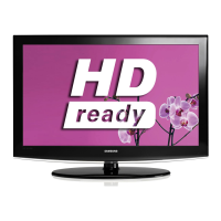
| HD Type | HD Ready |
| Aspect Ratio | 16:9 |
| Viewing Angle | 178 degrees |




 Loading...