Do you have a question about the Samsung RF23R6 Series and is the answer not in the manual?
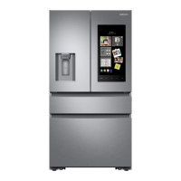
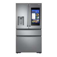
Overview of key cooling and door functions.
Electrical, performance, and refrigeration system details.
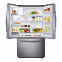
Visual guide to internal components and layout.
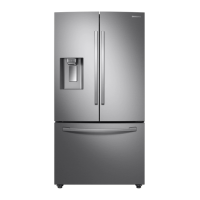
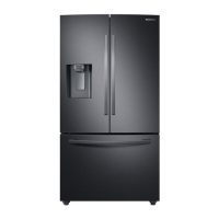
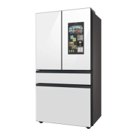
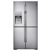
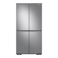
Comparison of model sizes, capacities, and weights.
Physical dimensions for installation.
Details on optional parts and codes.
Safety guidelines before disassembly.
Procedure for removing the refrigerator door.
Steps to remove the refrigerator door handle.
Steps to remove the freezer door handle.
Disassembly of the water dispenser lever.
Method for removing glass shelves.
Disassembly of foldable glass shelves.
Removing the vegetable/fruit drawer shelf.
Instructions for disassembling the internal water filter.
Disassembly of Cool Select Pantry components.
Steps to remove the motor damper.
Guide for replacing the water filter.
Disassembly of the auto-fill system.
Procedure for removing the vertical hinged section.
Removing the refrigerator evaporator cover.
Instructions for removing the refrigerator evaporator.
Method for disassembling the freezer door.
Detailed steps for ice maker disassembly.
Procedure for freezer ice maker disassembly.
Steps to replace the freezer light.
Procedure for disassembling the freezer door switch.
Removing the freezer evaporator cover.
Instructions for removing the freezer evaporator.
Procedure for disassembling the compressor cooling fan.
Detailed steps for compressor disassembly.
Accessing and disassembling machine compartment components.
Steps for disassembling the main electronic control box.
Overview of diagnostic functions for identifying failures.
Procedure for manually initiating a defrost cycle.
Using self-diagnosis to detect sensor and system errors.
Performing self-diagnosis during normal operation.
Error codes and diagnostic methods for sensors.
Interpreting load condition display for operational status.
Correlating LED indicators with specific load operations.
Setting the refrigerator to Cooling Off mode.
Setting the refrigerator to Exhibition Mode.
Guide for accessing and modifying operational settings.
Navigating and controlling settings in option mode.
Tables for adjusting compartment temperature settings.
Adjusting the dispenser heater's operation rate.
Modifying pantry and mid-drawer temperature settings.
Adjusting water volume for the ice tray.
Modifying ice maker standby time.
Adjusting ice room temperature settings.
Modifying ice maker dropping temperature.
Flowcharts for diagnosing issues based on symptoms.
Troubleshooting ICE Maker sensor failures.
Continuation of R sensor troubleshooting.
Troubleshooting humidity sensor failures.
Diagnosing pantry drawer damper heater issues.
Troubleshooting when refrigerator fans are not working.
Diagnosing ice room fan operation issues.
Troubleshooting FF ice maker operational failures.
Troubleshooting FZ ice maker operational failures.
Diagnosing defrost heater issues.
Troubleshooting no-power issues.
Diagnosing inverter compressor non-operation.
Troubleshooting continuous alarm or buzzer sounds.
Diagnosing inner control panel (PBA) malfunctions.
Troubleshooting dispenser control panel (PBA) issues.
Steps to troubleshoot refrigerator compartment lamp failure.
Diagnosing issues with ice water supply.
Troubleshooting the FZ ice water supply valve.
Diagnosing problems with ice production.
Troubleshooting the ice cover route motor.
Diagnosing IR sensor issues for ice production.
Interpreting LED blinking patterns indicating protection functions.
Diagram of the main PCB with component locations.
Identification of connectors on the main control board.
Comprehensive system architecture and data flow overview.
| Brand | Samsung |
|---|---|
| Model | RF23R6 Series |
| Category | Refrigerator |
| Language | English |