Do you have a question about the Samsung RR39M7 Series and is the answer not in the manual?
Essential safety guidelines and warnings for handling the appliance.
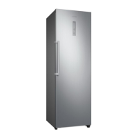
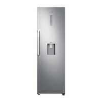
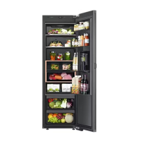
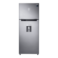
Overview of the key features and capabilities of the refrigerator.
Detailed specifications for the electrical components used in the refrigerator.
Technical drawings and measurements for refrigerator installation and clearance.
Guidelines for installing two refrigerators side-by-side.
Explanation of control panel buttons, display indicators, and their functions.
Important safety notes and tool requirements before disassembling the unit.
Instructions for removing and replacing door parts like the door itself and internal bins.
Procedures for removing shelves and drawers from the freezer and fridge compartments.
Steps for accessing and replacing internal parts like evaporators and electrical components.
Procedures for accessing and working with the machine compartment and compressor.
Guides for setting up dual installations and reversing door swing direction.
Procedures for activating and using forced operation and defrost test modes.
Steps for self-diagnosis and interpretation of error codes for troubleshooting.
Guides for special modes like load display, demo mode, and option settings.
Detailed troubleshooting steps for specific component failures and operational errors.
Layouts and connector descriptions for the main control board.
Layouts and connector descriptions for the inverter control board.
Detailed wiring diagrams showing component connections for different board configurations.
Functional block diagrams illustrating the interaction between major system components.
Table detailing model codes and their corresponding features and specifications.
Standard procedures and guidelines for refrigerant cycle repair and testing.
| Model Series | RR39M7 |
|---|---|
| Brand | Samsung |
| Category | Refrigerator |
| Climate Class | SN-T |
| Noise Level | 39 dB |
| Interior Light | LED |
| Refrigerant | R600a |
| Door Alarm | Yes |
| Reversible Door | Yes |
| Defrost System | Automatic |
| Shelf Material | Tempered Glass |
| Door Pocket Type | Various (depending on the specific model) |