2.6.2 Fuser unit component
The Fuser unit includes the following components:
1. Center heater lamp (LAMP1) / Side heater lamp (
These halogen lamps heat the drum-fuser belt. The
lamp (LAMP2) are lit alternately to heat the drum-fu
Each heater lamp has its coil in a different location.
the center, those of the side heater lamp (LAMP2) a
the drum-fuser belt so that they will not rotate separ
2. Drum-fuser belt
It receives heat from halogen lamp inside and condu
reduces warming up time and mode changing time.
the surface of the fuser belt is fluorinated. Rigid ass
surface of the fuser belt at nip and is pressed on the
ni
3. Pressure roller
The pressure roller is a rubber roller which ensures
fuser belt. It is driven by external driving mechanism
4. NC sensors
NC sensors detect the surface temperature of the ce
the heater lamps.
5. Thermistor (Center : 0.5mm-1.0mm distance, Sid
Thermistors, located at the center and rear end(non
overheating.
6. Thermostat
These thermostats cut off the power supply to the h
becomes abnormally hot as a result of problems suc
These thermostats are used to prevent abnormal op
replaced (as well as the other damaged parts in the
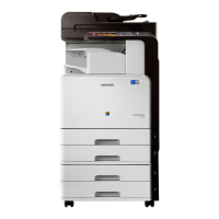
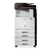
Service Manual
SCX-8030/8040 series
2-
enter heater lamp (LAMP1) and the side heater
he coil of the center heater lamp (LAMP1) is in
e on both sides. The heater lamps are fixed inside of
tely.
cts heat to toner and paper. The thin fuser belt
o prevent the fuser belt from adhering to the toner,
mbly located inside the fuser belt contacts inner
pressure roller by springs in order to ensured proper
roper nip width between the pressure roller and
and drives fuser belt by pressure.
nter and the rear end of the fuser belt which controls
mage position), protect the fusing system from
ater lamps by opening the circuit when the fuser belt
as a NC sensor malfunction.
ration. When the thermostat is triggered, it must be
user unit).
SAMSUNG ELECTRONICS
Version 0.05
 Loading...