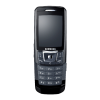
Do you have a question about the Samsung SGH D900i - Ultra Edition 12.9 Cell Phone 60 MB and is the answer not in the manual?
| Model | SGH-D900i |
|---|---|
| Category | Cell Phone |
| Series | Ultra Edition |
| 2G Network | GSM 900 / 1800 / 1900 |
| Status | Discontinued |
| Weight | 85 g |
| Display Type | TFT, 256K colors |
| Display Size | 2.1 inches |
| Display Resolution | 240 x 320 pixels |
| Memory card slot | microSD (dedicated slot) |
| Internal Memory | 60 MB |
| Primary Camera | 3.15 MP |
| Video | QCIF@15fps |
| Secondary Camera | No |
| Alert types | Vibration; Downloadable polyphonic, MP3 ringtones |
| Loudspeaker | Yes |
| 3.5mm jack | No |
| WLAN | No |
| Bluetooth | 2.0, A2DP |
| Radio | No |
| Messaging | SMS, MMS, Email |
| Browser | WAP 2.0/xHTML |
| Games | Yes |
| Java | Yes, MIDP 2.0 |
| Battery Type | Removable Li-Ion 800 mAh battery |
| Battery Capacity | 800 mAh |
| Stand-by | Up to 300 h |
| Dimensions | 12.9 mm |
| Pixel Density | 190 ppi |
| USB | v2.0 |
Guidelines for safe and proper repair procedures, tools, and environment.
Measures to prevent damage to sensitive electronic components from electrostatic discharge.
Technical specifications for GSM network bands, frequencies, and modulation.
Details on transmit power levels for different GSM bands and control levels.
Transmit power class specifications for GSM EDGE technology.
Overview of the mobile phone's primary features and capabilities.
Procedures for adjusting software settings related to phone operation.
Steps and prerequisites for downloading software onto the device.
Diagram showing all components of the phone disassembled for identification.
Comprehensive list of all parts with their design location and SEC codes.
Step-by-step guide on how to take apart and reassemble the phone.
Block diagram illustrating the radio frequency signal path and components.
Block diagram detailing the Bluetooth subsystem architecture.
Block diagram of the baseband processing unit and its interfaces.
Diagram showing component layout on the top side of the printed circuit board.
Diagram showing component layout on the bottom side of the printed circuit board.
Flowchart for diagnosing issues related to the device not powering on.
Flowchart for troubleshooting initial startup failures or basic operation issues.
Flowchart for diagnosing problems with the phone's charging system.
Flowchart to diagnose issues with SIM card detection or functionality.
Flowchart for troubleshooting microphone or audio input problems.
Flowchart to diagnose issues with the speaker or melody playback.
Flowchart for diagnosing problems with keypad input and display feedback.
Flowchart for troubleshooting issues with the phone's receiver.
Flowchart for diagnosing problems with the main LCD backlight.
Flowchart for troubleshooting issues with the keypad backlighting.
Flowchart for diagnosing problems with the camera function.
Flowchart for diagnosing GSM receiver signal reception issues.
Flowchart for diagnosing GSM transmitter signal output issues.
Flowchart for diagnosing DCS receiver signal reception issues.
Flowchart for diagnosing DCS transmitter signal output issues.
Flowchart for diagnosing PCS receiver signal reception issues.
Flowchart for diagnosing PCS transmitter signal output issues.
Flowchart for diagnosing Bluetooth connectivity or functionality problems.
Flowchart for diagnosing general radio reception or transmission issues.