The provided document is a service manual for a range of Samsung Video Cassette Recorders (VCRs), specifically models SV-610X/210X, SV-614B/210B, and SV-480G/470G. This manual, published in June 1998, serves as a comprehensive guide for technicians and service personnel, detailing the necessary procedures for the maintenance, repair, and adjustment of these VCR units.
Function Description:
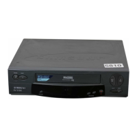
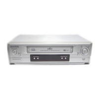
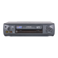
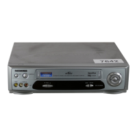
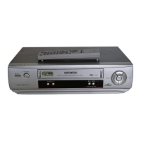
These devices are Video Cassette Recorders, designed for the recording and playback of video and audio content stored on magnetic tape cassettes. As VCRs, their primary function is to allow users to watch pre-recorded content (such as movies or TV shows) and to record television broadcasts for later viewing. The front panels of the VCRs shown in the manual illustrate standard controls for these functions, including:
- POWER: To turn the unit on or off.
- EJECT: To remove a video cassette from the tape mechanism.
- SYSTEM: Likely a button for accessing system settings or menus.
- REW (Rewind): To rapidly rewind the tape to an earlier position.
- F.F (Fast Forward): To rapidly advance the tape to a later position.
- PLAY: To begin playback of the video cassette.
- STOP: To halt playback or recording.
- REC (Record): To initiate recording onto a video cassette.
- PROGRAM: Likely used for setting up timed recordings of television programs.
- OPEN: On the SV-480G model, this might refer to opening a front panel or a specific compartment.
The presence of these controls indicates that the VCRs offer a full suite of standard video recording and playback capabilities, typical of consumer electronics from that era.
Important Technical Specifications (Inferred from Manual Structure):
While the manual itself does not explicitly list technical specifications on the cover or initial pages, its table of contents provides strong indicators of the detailed information contained within. Key sections that would cover technical specifications include:
- 3. Product Specifications and Comparison Chart: This section would provide precise technical details such as video formats (e.g., VHS, S-VHS), audio capabilities (e.g., Hi-Fi Stereo), recording speeds (e.g., SP, LP, EP), tuner specifications, power requirements, dimensions, weight, and possibly regional compatibility (e.g., NTSC, PAL, SECAM). The "Comparison Chart" suggests that there might be differences in features or specifications across the various models covered (SV-610X/210X, SV-614B/210B, SV-480G/470G), which would be detailed here.
- 8. Block Diagrams: These diagrams would illustrate the high-level architecture of the VCR's electronic systems, showing how different functional blocks (e.g., tuner, video processor, audio processor, tape transport control, power supply) are interconnected. This provides insight into the overall design and signal flow.
- 9. PCB Diagrams: Printed Circuit Board diagrams would show the layout of components on the various circuit boards within the VCR, crucial for identifying specific parts and troubleshooting.
- 10. Wiring Diagram: This would detail the internal wiring connections between different PCBs, modules, and external connectors, essential for assembly and repair.
- 11. Schematic Diagrams: These are detailed circuit diagrams showing all individual electronic components (resistors, capacitors, ICs, transistors, etc.) and their connections, along with voltage and signal paths. This is the most granular level of technical specification for the electronic design.
The manual also references a separate "Mechanical Manual" (DX7-A/AC, DX8-A/AC — AC68-20392A) for "mechanical disassembly and adjustment." This indicates that the VCRs incorporate complex mechanical tape transport mechanisms, which require precise adjustments for optimal performance. These mechanical specifications would include details about the tape path, head drum assembly, motor types, and gear systems.
Usage Features (Inferred):
Based on the model names and the era, these VCRs would have offered a range of user-friendly features common at the time:
- Multi-Speed Recording: Likely supporting standard play (SP) and extended play (LP/EP) modes to maximize recording time on a single cassette.
- Timer Recording: The "PROGRAM" button suggests the ability to set up future recordings, a fundamental feature for capturing TV shows. This would typically involve setting the date, time, channel, and duration.
- On-Screen Display (OSD): Most VCRs of this generation featured OSD for easier navigation of menus, programming, and status indicators.
- Remote Control Capability: While not explicitly shown, VCRs were almost universally operated via remote control for convenience.
- Auto Tracking: Automatic adjustment of the video heads to ensure optimal picture quality during playback.
- Front Panel Controls: As depicted, essential controls are available directly on the unit for basic operation.
- Input/Output Connectivity: VCRs typically included RF coaxial inputs/outputs for antenna/cable connections, and composite video/audio (RCA) inputs/outputs for connecting to TVs, camcorders, or other video equipment. Some higher-end models might have included S-Video.
The distinction between models like SV-610X/210X and SV-480G/470G might indicate different feature sets, such as varying levels of picture quality enhancement, audio capabilities (e.g., Hi-Fi Stereo vs. mono), or tuner sophistication. The "X" and "B" suffixes could denote different regional versions or minor feature variations.
Maintenance Features:
The service manual itself is a primary maintenance feature, providing all the necessary information for professional servicing. Key sections dedicated to maintenance include:
- 1. Precautions: Essential safety warnings and guidelines for technicians to prevent injury or damage to the device during servicing.
- 4. Disassembly and Reassembly: Step-by-step instructions for taking the VCR apart and putting it back together, crucial for accessing internal components for repair or cleaning.
- 5. Alignment and Adjustment: Detailed procedures for calibrating various parts of the VCR, including mechanical adjustments (e.g., tape path, head drum alignment) and electronic adjustments (e.g., tuner alignment, video/audio signal calibration) to ensure optimal performance after repair or component replacement.
- 6. Exploded View and Parts List: Diagrams showing all individual components of the VCR in an exploded view, along with a corresponding list of part numbers. This is vital for ordering replacement parts.
- 7. Electrical Parts List: A comprehensive list of all electrical components, including their specifications and part numbers, for troubleshooting and replacement.
- UPDATE LOG SHEET: A dedicated page for recording any special servicing information, service bulletins, or part number changes, ensuring that technicians have the most current information. This highlights Samsung's commitment to providing ongoing support and updates for their products.
The existence of a separate "Mechanical Manual" underscores the complexity of VCR mechanics and the specialized knowledge required for their maintenance. This separation suggests that mechanical servicing, particularly the intricate tape transport system, is a critical aspect of VCR maintenance, requiring precise adjustments to ensure reliable tape loading, playback, and recording without damaging the tape or the machine.
In summary, this service manual for Samsung VCRs SV-610X/210X, SV-614B/210B, and SV-480G/470G is an indispensable resource for anyone involved in the technical support and repair of these devices, covering everything from basic operation to detailed circuit diagrams and mechanical adjustments.