Do you have a question about the Samsung Xpress C480 Series and is the answer not in the manual?
Details warnings for service technicians and user safety regarding high voltages and lasers.
Outlines precautions against toxic materials and electric shock hazards.
General handling guidelines for personal safety and product care, including environmental factors.
Key precautions for part replacement, handling PBAs, and releasing plastic latches.
Critical warnings about high temperatures, moving parts, and safe lifting techniques.
Guidelines for preventing damage from electrostatic discharge to sensitive components.
Lists key specifications like printing speed, memory, processor, and interface options.
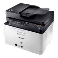
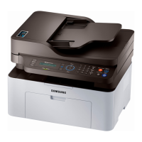
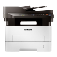
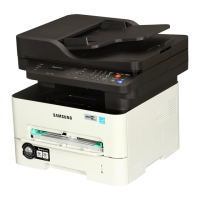
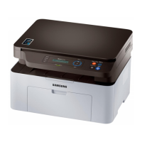
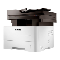
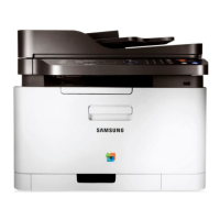
Describes the physical models and their general features.
Details technical specifications for various functions like print engine and copy.
Specifications for the scanning functions, including speed and resolution.
Specifications for the fax capabilities of compatible models.
Details the printer's internal controller, supporting OS, and interface specifications.
Specifies paper input capacities and media types supported by the printer.
Provides data on monthly usage volume and maximum monthly duty.
Details operating temperature, humidity, and acoustic noise levels.
Lists toner cartridge and imaging unit yields based on ISO standards.
Details part codes and average yields for common maintenance components.
Explains the printer's main components and their functions.
Illustrates and labels the printer's front components.
Illustrates and labels the printer's rear components.
Diagrams the path paper takes during the printing process.
Details the arrangement of mechanical and hardware parts within the printer.
Explains the cassette and pick-up roller functions for paper feeding.
Describes the transfer roller's function in delivering toner to the paper.
Explains the drive unit's components, including motor and gears.
Details the fuser unit's components and operation for fusing toner.
Explains the function of the Laser Scanner Unit in creating latent images.
Describes toner cartridge and imaging unit functions and life spans.
Lists the electrical components and circuit boards of the printer.
Details the main processor, its capabilities, and board connections.
Explains the Operator Panel/Display board's composition and communication.
Details the fax board's components and function in sending/receiving.
Describes the connection board's role linking clutch/sensor boards to the main board.
Explains the CTD board's function in compensating color tone density.
Details the CRUM board's connections for signals, power, and sensors.
Describes the USB Host board providing the USB port for memory sticks.
Outlines the Wireless LAN module's specifications and network communication.
Details the SMPS board's power conversion functions and specifications.
Describes the HVPS board's function in generating high voltage.
Information on the NFC tag sticker for near field communication.
Shows the location of various sensors and electrical parts within the printer.
Explains the firmware control algorithm for engine functions like feeding and transfer.
Explains the fusing process and related heat errors like Open, Low, and Over Heat.
Describes LSU errors such as Lready and Hsync signal abnormalities.
Overview of the printer's software architecture including host software and firmware.
Explains how data and control signals flow between the host and firmware.
Essential safety and handling guidelines before servicing, including part number verification.
Key precautions for part replacement, noting screw locations and avoiding force.
Specific advice for handling Printed Circuit Board Assemblies (PBAs) to prevent static damage.
Method for safely releasing plastic latches on parts to avoid breakage.
Lists screw types, part codes, and locations for disassembly and reassembly.
Procedures for replacing common maintenance components like the ITB unit.
Step-by-step guide to remove and replace the ITB Unit.
Instructions for replacing the Fuser Unit, including screw and connector removal.
Steps for replacing the Transfer (T2) roller.
Procedure to replace the pick-up roller.
Guides for replacing major service parts like covers and ADF units.
Steps to remove and replace the printer covers.
Instructions for replacing the Automatic Document Feeder unit.
Procedure for replacing the Operator Panel/Display unit.
Steps to remove and replace the platen scanner unit.
Guide for replacing CIS and Scan Drive components.
Steps to remove the middle cover.
Instructions for replacing the fax board.
Procedure for removing and replacing the HVPS board.
Steps to remove and replace the Laser Scanner Unit.
Guide for disassembling the paper path frame.
Instructions for removing regi clutch and pick up solenoid.
Steps for removing feed and empty sensors.
Procedure for removing the main system board.
Steps to remove the SMPS power supply board.
Procedure for removing the cam solenoid.
Instructions for removing the main drive unit.
Covers machine adjustments, maintenance tests, and basic operations.
Explains the functions of the control panel buttons.
Interprets the meaning of different LED status indicators for machine status.
Procedures for clearing paper jams from the document feeder and printer.
Steps to remove jammed documents from the Automatic Document Feeder.
Procedures for removing jammed paper from the input tray and inside the machine.
Explains useful menu options for service tasks like monitoring supplies and adjusting altitude.
How to check toner and other supply levels via the control panel menu.
Adjusts settings for optimal print quality based on the machine's altitude.
Instructions for printing various machine reports for maintenance and diagnosis.
Adjusts color settings such as contrast, color registration, and density.
Identifies image defects caused by faulty or damaged rollers.
Tools for managing the printer remotely or locally via web or application.
Steps to set up and use the web-based management tool for printer configuration.
Application for managing printer settings, status, and alerts.
Instructions for updating the printer firmware via USB or network.
Steps to update firmware using the USB port and provided tool.
Steps to update firmware using the network connection and SyncThru service.
Accessing and using the service diagnostic mode for malfunction analysis.
Procedures to enter the service technician mode on the control panel.
Overview of the options available in tech mode for testing and diagnostics.
Settings for fax transmission, dial parameters, and modem speed.
Tests for hardware components like keys, modem, DRAM, and CIS.
Options for printing reports like protocol dump, supplies info, and configuration.
Settings for NVM initialization and configuration values.
Guide to writing data to NFC tags using a mobile application.
General guide for diagnosing and resolving printer issues based on symptoms.
A flowchart for initial symptom diagnosis before repair.
A checklist for basic troubleshooting steps including power, LEDs, and paper path.
Lists error codes and their corresponding troubleshooting pages.
Diagnoses and resolves common image quality issues like lines, bands, and density.
Describes and solves vertical black lines in prints caused by roller contamination.
Addresses vertical white voids in images caused by LSU or roller issues.
Addresses contamination on the back of printed pages caused by dirty rollers.
Troubleshoots issues causing dark or black printouts, often related to HVPS.
Solves the problem of printing blank pages, related to contacts or LSU.
Fixes issues with uneven print density, often caused by toner or ITB unit.
Addresses dark or white horizontal stripes on prints, potentially from roller contamination.
Troubleshoots issues where toner does not fix properly to paper, often a fuser issue.
Visual representation of the printer's internal components and their interconnections.
Illustrates how various electronic components and boards are interconnected.
Lists recommended tools for safe and easy troubleshooting procedures.
Defines common technical terms used in the manual for better understanding.
Lists the versions and changes made to the document over time.
| Print Technology | Laser |
|---|---|
| Functions | Print, Copy, Scan |
| Print Speed (Color) | Up to 4 ppm |
| Print Resolution | Up to 2400 x 600 dpi |
| Duplex Printing | Manual |
| Processor | 800 MHz |
| Memory | 128 MB |
| Input Capacity | 150 sheets |
| Output Capacity | 50 sheets |
| Scan Resolution (Optical) | Up to 1200 x 1200 dpi |
| Scan Resolution (Enhanced) | Up to 4800 x 4800 dpi |
| Copy Speed (Color) | Up to 4 cpm |
| Copy Resolution | Up to 600 x 600 dpi |
| Maximum Copy Size | A4 |
| Wi-Fi | Yes |
| Monthly Duty Cycle | Up to 20, 000 pages |
| Weight | 12.89 kg |
| First Print Out Time (Color) | 26 seconds |
| Media Sizes Supported | A4, A5, A6, B5, Legal, Letter, Executive, Folio, Oficio |
| Media Types Supported | Plain, Bond, Recycled, Thick, Labels |
| Scan to | PC |
| Copy Speed (Black) | 18 cpm |
| Zoom Range | 25% - 400% |
| Interface | Hi-Speed USB 2.0 |
| Mobile Printing | Samsung Mobile Print, Google Cloud Print |
| Connectivity | USB |
| Supported Operating Systems | Windows, Mac, Linux |
| Dimensions (W x D x H) | 406 x 362 mm |
| Print Speed (Black) | Up to 18 ppm |