Do you have a question about the Sandel SG102 Series and is the answer not in the manual?
Legal disclaimer regarding installation and compatibility of equipment with the SG102.
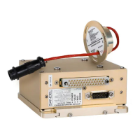
Overview of the Sandel SG102 AHRS, its functions, and the scope of this manual.
Explains strapdown AHRS operation and critical installation requirements, emphasizing precise alignment.
Details the SG102's intended use, available output formats, and system compatibility.
Describes technical characteristics, approval basis, properties, and installation requirements.
Details the different SG102 models (MOD 1, MOD 2, SG102/D) and their variations.
Lists the part numbers for SG102 and MT102 based on aircraft type and variation.
Outlines approval basis, TSOs, software certification, and installation approval procedures.
Covers dimensions, environmental summary, operational specifications, and ARINC labels.
Provides instructions for carefully unpacking and visually inspecting the equipment for damage.
Covers planning, mounting orientation, base alignment, and KG102 replacement applications.
Details general requirements, power, cooling, slaving, outputs, and discrete signals.
Covers mounting orientation, rigid airframe attachment, and general hardware instructions.
Details the step-by-step process for aligning the SG102 mounting base to the aircraft axis.
Outlines essential post-installation verification steps like continuity and ground tests.
Details the pin assignments and signal types for the P-1 connector.
Details the pin assignments and signal types for the P-2 connector.
Compares the MT102 to traditional fluxgates, highlighting its solid-state advantages.
Covers environmental considerations, wiring methods, and installation alignment for the MT102.
Details the pin assignments and signal types for the MT102's environmentally sealed connector.
Covers utility software, adapter use, orientation select, compass calibration, labels, and updates.
Explains the function and meaning of the front panel LEDs for SG102 and SG102/D.
Lists LED error codes, their flash patterns, and corresponding failure causes.
Covers physical installation, wiring verification, system functions, and calibration checks.
Details NAV/COM testing, general equipment interaction, and other appliance interference tests.
| Brand | Sandel |
|---|---|
| Model | SG102 Series |
| Category | Accessories |
| Language | English |