Do you have a question about the S&P CONTROL ECOWATT and is the answer not in the manual?
Details the AC/DC model with analogical output for DC motors or frequency converters.
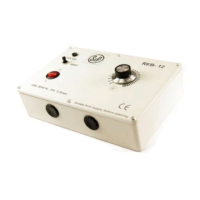
Details the AC/4A model with single-phase AC input and voltage output for single-phase motors.
Instructions for mounting in a technical room and fixing to a vertical wall with cable glands.
Specifies the power supply range for the AC/DC model (90-260VAC).
Specifies the power supply for the AC/4A model (230VAC).
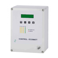
Explains the digital display showing input and output values and adjustment settings.
Details the measured values by sensors S1 (humidity), S2 (CO2), and S3 (temperature).
PI control with analogical input (0-10V / 4-20mA).
Control with three analogical inputs (0-10V / 4-20mA).
Control with three digital inputs.
Procedure to change the operating mode using front panel keys.
Setup for constant pressure system operation using S1 input.
Setting the pressure set point and sensor range for proportional mode.
Adjusting motor response based on network pressure changes.
Selecting the measurement unit and type for sensor channel 1.
Configuring the sensor's range, average value, and alarm threshold.
Setting up input types and parameters for sensors 2 and 3.
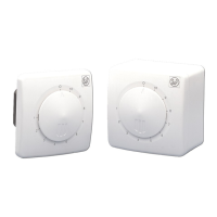
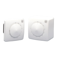
Operation with contact inputs (NO/NC) for speed control based on input changes.
Configuration of contact inputs, setting between normally open (NO) and normally closed (NC).
Steps to reset the device to factory default settings via button combination.
Adjusting the minimum and maximum output signal levels.
Adjusting slave output and setting Hall pulses for RPM indication.
Function of Relay 1 (J13) for alarm or error indication with the ERROR LED.
Function of Relay 2 (J5) for activating high speed in MIN-MAX mode.
Protection index, material, dimensions, storage, and operating environment limits.
Electrical insulation, conformity marking (CE), and critical safety recommendations for installation and handling.
| Brand | S&P |
|---|---|
| Model | CONTROL ECOWATT |
| Category | Controller |
| Language | English |