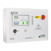
Do you have a question about the S&S Northern Merlin 3000S and is the answer not in the manual?
| Brand | S&S Northern |
|---|---|
| Model | Merlin 3000S |
| Category | Security Sensors |
| Language | English |
Crucial safety advice and precautions for using the Merlin 3000S system.
Describes control panel mounting and access to the circuit board (PCB).
Specifies optimal placement for CO2 monitors.
Specifies optimal placement for CO detectors.
Specifies optimal placement for optical sensors.
Specifies optimal placement for duct temperature sensors.
Recommends placement for speed controllers to avoid electrical noise.
Mains input 100-240VAC, fused at 3A.
Power output for the gas solenoid valve (100-240VAC).
Output for electrical contactor (100-240VAC), fused at 3A.
Input signal from air pressure switches or current monitors.
Input signal from air pressure switches or current monitors.
Low voltage connections for Building Management Systems (BMS).
Output switches with key, links to fan switch for power.
Output switches with key, links to fan switch for power.
Connects to the gas pressure transducer.
Terminal for remote emergency shut-off buttons.
Connections for a Merlin Carbon Monoxide (CO) gas detector.
0-10VDC signal from CO2 monitor for fan speed control.
0-10VDC signal from CO2 monitor for fan speed control.
Linked out connection for a Merlin Carbon Dioxide (CO2) monitor.
Low voltage connection for turbine gas meter input.
Terminal for fire alarms.
Permanent 12V DC output for powering monitors.
Wired to optical sensor for smoke/steam detection.
Connection to duct temperature sensor for fan speed control.
Wired to optical sensor for smoke/steam detection.
Connection to duct temperature sensor for fan speed control.
Regulates external extract fan speed controllers via 0-10VDC output.
Regulates external supply fan speed controllers via 0-10VDC output.
Details how to turn the unit ON and OFF using the key switch.
Explains how to activate and deactivate boost mode for maximum fan speed.
Instructions on changing screen brightness levels.
Describes the screen display while fans reach their set speed.
Lists and describes options available in the Settings 1 menu.
Lists and describes options available in the Settings 2 menu.
Instructions on navigating and modifying system settings.
Detailed explanations of each setting available in the Settings 1 menu.
Detailed explanations of each setting available in the Settings 2 menu.
Warning indication for high CO2 levels and corresponding fan response.
Warning indication for smoke/steam detection and fan speed.
Warning indication for high duct temperature and fan speed.
Action taken when an emergency stop button is pressed.
Fault condition for high CO gas concentration.
Fault condition for high CO2 gas levels.
Fault condition when a fire alarm is triggered.
Fault for low gas pressure and system shutdown.
Fault condition when the gas pressure test fails.
Fault condition for supply fan failure.
Fault condition for extract fan failure.