CD-E7 70
8. ADJUSTMENTT
C
• Cautions
1.
Turn
the
power
OFF before reffioving the bonnet.
2.
See Figure
8-1
on page 19 for the locations
where
adjustments are to
be carried out.
3.
Use the EIAJ test disk
CD-1.
4.
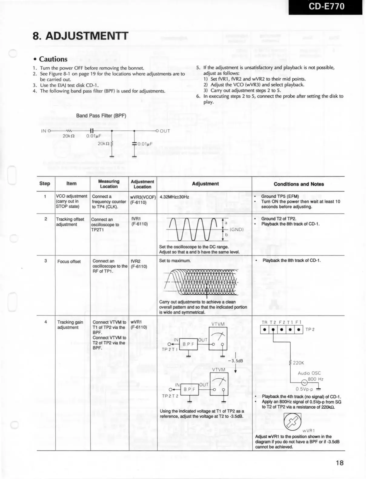
The following band
pass
filter (BPF) is used for adjustments.
5.
If the adjustment is unsatisfactory and playback is not possible,
adjust
as follows:
1)
Set fVRI, fVR2 and wVR2 to their mid points.
2)
Adjust the VCO (wVR3) and select playback.
3)
Carry out adjustment steps 2 to 5.
6.
In executing steps 2 to 5, connea the
probe
after setting the disk to
play.
Band
Pass
RIter (BPF)
IN O-
-\ \ -
20kn
O.OIMF
20kn
-OOUT
:O.OIMF
Step
Item
Measuring
Location
Adjustment
Location
Adjustment
Conditions and Notes
VCO adjustment
(carry out in
STOP state)
Connect a
trequency counter
toTP4(CLK).
wVR3(VCOF)
(F-6110)
4.32MHz±30H2
Ground
TP5 (EFM)
Turn
ON the
power
then wait at
least
10
seconds
before adjusting.
c
Tracking offset
adjustment
Connect an
oscllloscope
to
TP2T1
fVRI
(F-6110)
Ground
T2otTP2.
Playback
the
8th
track of
CD-1.
(GND)
Set
ttie
oscllloscope to the DC range.
Adjust so that a
and b
have the
same
level.
Focus
offset
Connect an
oscllloscope
to the
RFofTPL
fVR2
(F-6110)
Set
to maximum.
Playback
the 8th
track
of
CD-1.
Carry out adjustments to achieve a
clean
overall pattern and so that the indicated
portion
is
wide
and
symmetrical.
c
Tracking gain
adjustment
Connect
VTVM
to
Tl ofTP2viathe
BPF.
Connect
VTVM
to
T2ofTP2viathe
BPF.
wVRI
(F-6110)
VTVM
IR
T2 F2 Tl Fl
IN
TP2T I
B
P F
T
'OUT
-O Q
TP2
-3.5dB
VTVM
IN
TP2T 2
BPF
OUT
-O Q
220K
Using
the
indicated
voltage
at
Tl of TP2
as
a
reference, adjust the
voltage
at
T2 to
-3.5dB.
Audio
OSC
^800
Hz
O.SVp-p"?!?
Playback
the
4th
track (no signal) of
CD-1.
Apply
an
800Hz
signal
of 0.5Vp-p
trom
SG
to T2 of TP2
via
a
resistance
of
220kQ.
wVRl
Adjust
wVRI
to the positlon
shown
in
the
diagram
if
you do not have a
BPF
or if
-3.5dB
cannot be achieved.
18
 Loading...