− 8 −
(2) Description of Operation
When power is turned on, the sub-processor and ASIC are
reset, the programs in the flash ROM are loaded to the ASIC,
and the ASIC start functioning.
(2-1) When Operated Independently
The video input signal passes through the filter, eliminating
high end noise, and then enters the decoder.
The video signal is digitized at the decoder, the brilliance
signal is separated from the chroma signal, and from there
the chroma signal is separated into chrominance signals.
The data for the separated brilliance and chrominance sig-
nals is input to the ASIC.
Once stored in the SDRAM, the data is converted to JPEG
in order, and the converted data is stored in SDRAM. The
stored compressed data is written to the hard disk at suit-
able times.
UART is used for writing data needed for service, and the
PC Card and CF Card are written through the I/F.
The playback images are read from the hard disk, and once
stored on the SDRAM, they are expanded in order.
The image data enters the Video Encoder from the bus, and
then is combined with the image signal.
The analog brilliance and chroma signals are made by D/A
and then output from ASIC.
The Y signal output from ASIC is passed through the filter
along with the chroma signal with the synch signal attached,
converted to VIDEO signal by the YC mix circuit, and then
output.
(2-2) When Connected with a Digital Interface
Image data from a multiplexer that has been serial digitized
is converted to parallel data by the deserializer and passes
over the bus.
Parallel data output by the ASIC is serialized by the serializer,
and is then connected to devices with digital interfaces such
as a multiplexer.
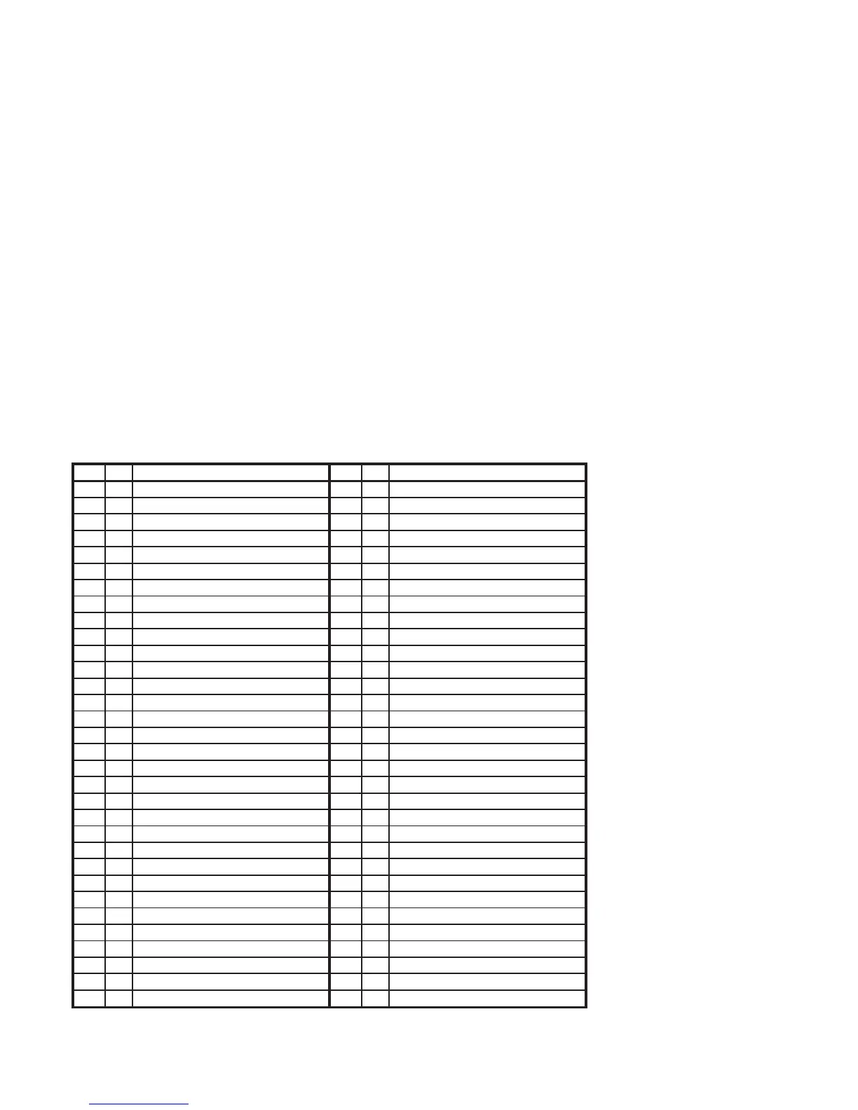
PIN I/O FUNCTION PIN I/O FUNCTION
1 O ASIC SCK 33 B
I2CD1 (Data for E2P Decoder)
2 O 232TD 34 O
I2CC1 (Clock for E2P Decoder)
3 I 232RD 35 - GND
4 O 232RTS 36 - 5V
5 I Power Fail 37 O HDD full out
6 O BUZZER 38 O Alarm full out
7 O RS232C USE 39 O Warning out
8 O RS CTL 40 O Non Rec out
9 - 5V 41 O Sensor Alarm out
10 - GND 42 I Alarm reset
11 I SHUTTLE-1 43 I Alarm in
12 I SHUTTLE-2 44 I Clock set in/out
13 I SHUTTLE-3 45 O ASIC Reset
14 I SHUTTLE-4 46 I Option 0
15 I FAN IN 47 I Option 1
16 I SVHS IN 48 I Option 2
17 I NIRMAL(L)/LOW END(H) 49 I Read Vd IN
18 I Series IN 50 I JOG1
19 O Audio Mute 51 I JOG2
20 O Control Select0 52 I S.REQ
21 O Control Select1 53 - RESET
22 O Series OUT 54 - X'tal OSC in
23 O
D Through(H)/Signal OUT(L)
55 - X'tal OSC out
24 O Degital in Reset 56 - GND
25 O V Mute H 57 - Ceramic OSC in
26 O Degital out Reset 58 - Ceramic OSC out
27 O FULL LED 59 - 5V
28 O Alarm FULL LED 60 I KEY_IN0 (AD poart)
29 O LOCK LED 61 O MENU H
30 O ALARM LED 62 I REMOCON IN (AD poart)
31 O EXP_CLK1 63 O ASIC SO
32 O EXP_DATA 64 I ASIC SI
IC271 PIN FUNCTIONS TABLE

 Loading...