– TABLE OF CONTENTS –
Adjustment Procedures . . . . . . . . . . . . . . . . . . . ...1
Test Procedures and Troubleshooting . . . . . . . . . . 4–ICI
Specifications . . . . . . . . . . . . . . . . . . . . . . . . . ...2
Disassembly Instructions . . . . . . . . . . . . . . . . . 11-14
Power Output Measurement . . . . . . . . . . . . . . . . . . . 2
Exploded View and Parts List . . . . . . . . . . . . . . 15-2(J
Precautions and Repair Service Tips . . . . . . . . . . . . . . 2
Overall Circuit Diagram . . . . . . . . . . . . . . . . . . . . . 21
Circuit Diagram . . . . . . . . . . . . . . . . . . . . . . . . ...3
CAUTION
MICROWAVE RADIATION
PERSONNEL SHOULD NOT BE EXPOSED TO THE
MICROWAVE ENERGY WHICH MAY RADIATE
FROM THE MAGNETRON OR OTHER MICRO-
WAVE GENERATING DEVICE IF IT IS impro-
perly USED OR CONNECTED. ALL INPUT AND
OUTPUT MICROWAVE CONNECTIONS, WAVE-
GUIDES, FLANGES, AND GASKETS MUST BE
SECURE. NEVER OPERATE THE DEVICE WITH-
OUT A MICROWAVE ENERGY ABSORBING
LOAD ATTACHED. NEVER LOOK INTO AN
OPEN WAVEGUIDE OR ANTENNA WHILE THE
DEVICE IS ENERGIZED.
1. ADJUSTMENT PROCEDURES
TO AVOID POSSIBLE EXPOSURE TO MICROWAVE
ENERGY LEAKAGE, THE FOLLOWING ADJUST-
MENT OF THE INTERLOCK SWITCHES SHOULD BE
MADE ONLY BY AUTHORIZED SERVICE PERSON-
NEL.
PRIMARY
INTERLOCK SWITCH,
INTERLOCK
MONITOR SWITCH AND DOOR SENSING SWITCH
ADJUSTMENT
(Figure 1)
(1)
(2)
(3)
(4)
(5)
(6)
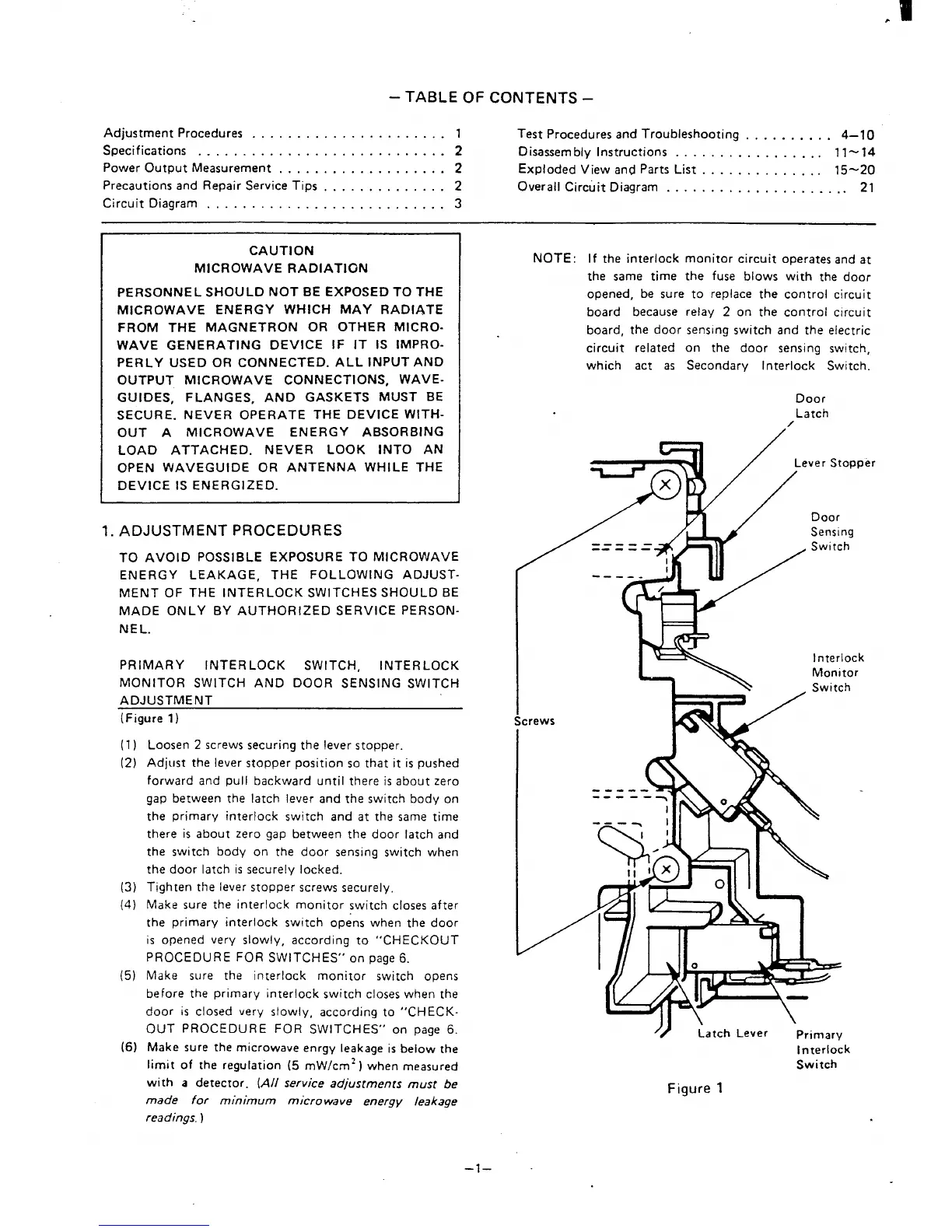
Loosen 2 screws securing the lever stopper.
Adjust the lever stopper position so that it is pushed
forward and pull backward until there is about zero
gap belween the latch lever and the switch body on
the primary interlock switch and at the same time
there is about zero gap between the door latch and
the switch body on the door sensing switch when
the door latch is securely locked.
Tighten the lever stopper screws securely.
Make sure the interlock monitor switch closes after
the primary interlock switch opens when the door
is opened very slowly, according to “CHECKOUT
PROCEDURE FOR SWITCHES” on page 6.
Make sure the interlock monitor switch opens
before the primary interlock switch closes when the
door is closed very slowly, according to “CHECK-
OUT PROCEDURE FOR SWITCHES” on page 6.
Make sure the microwave enrgy leakage is below the
limit of the regulation (5 mW/cm* ) when measured
with a detector. (A//
made for minimum
readings. )
service adjustments must be
micro wave energy leakage
NOTE: If the interlock monitor circuit operates and at
the same time the fuse blows with the door
opened, be sure to replace the control circuit
board because relay 2 on the control circuit
board, the door sensing switch and the electric
circuit related on the door sensing switch,
which act as Secondary Interlock Switch.
Door
Latch
/
-----
Stopper
I
Screws
Door
Sensing
Switch
Interlock
Monitor
Switch
/“
Latch Lever
Primary
Interlock
Switch
Figure 1
–l–
 Loading...