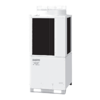
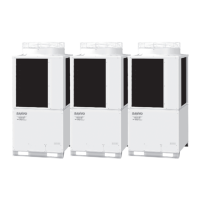
8hp
Refrigerant (gas tube)
brazed
connection
flared
connection
flared
connection
Refrigerant (liquid tube)
Refrigerant (balance tube)
– 15
Wind direction
Wind direction
(Installation hole pitch)
(Top panel dimension)
(Installation hole pitch)
(Top panel dimension)
(Max.)
(Bottom plate dimension)
(Bottom plate dimension)
Installation brac
k
et mounting surface
(Knoc
k-out hole)
(Knoc
k-out hole)
Refrigerant (front: knockout hole and slit)
Tubing port (bottom: hole with cover)
Electrical wiring port (front:
ø60, ø28 knock-out holes – for conduit connection)
Electrical wiring port (bottom:
ø60, ø38 knock-out holes – for conduit connection)
Pressure outlet port (for high pressure:
ø7.94 Schrader-type connection)
Pressure outlet port (for low pressure:
ø7.94 Schrader-type connection)
Knock-out hole for connecting pressure gauge (optional)
10hp 12hp 14hp 16hp
Left side
Right side
Front view
Installation holes (4
Top view
Z view
Space for creation of hole on-site (Max. diameter ø48)
Size (mm)
Table of Measurements for Refrigerant Tube Connection
Holes used
for transport
∗
Measurements for 10–16hp
assume that the supplied
connection tubing is used.
Equivalent
horsepower
Enlarged view of A
6
8
4
11
5
7
×
20 elongated holes), anchor bolts M12 or larger
Refrigerant
SPW-C0705, C0905, C1105, C1305, C1405DXHN8
1. Outdoor Unit
1-2. Dimensional Data

 Loading...


