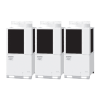
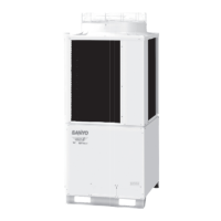
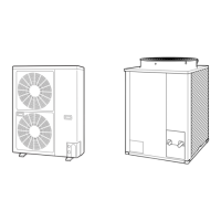
-C0905DZH8
-C1155DZH8
SPW-C0705DZH8
High pressure
sensor
Solenoid
Electronic
Oil
separator
Balance tube
tube
Accumulator
Strainer
Compressor
Compressor
Oil drain
Indoor unit Indoor unit
(not supplied)
Discharge tube
Suction tube
(Purchased separately)
(INV)
High pressure switch
Low pressure sensor
Distribution joint kit
For LP
Narrow tube
For HP
To outdoor unit
Fusible plug
Solenoid valve kit
Capillary
4-way valve
valve
control valve
(AC1)
(for 0705-1155 model: ø9.52)
(1155 model: ø25.4)
(0905 model: ø22.22)
(0705 model: ø19.05)
(0905, 1155 model: ø19.05)
(0705 model: ø15.88)
(1155 model: ø12.7)
(0705, 0905 model: ø9.52)
4-24
3-WAY ECO-i SYSTEM Unit Specifi cations
1
2
3
4
5
6
7
8
1-4. Refrigerant Flow Diagram
1. Outdoor Unit
TD831143-00W-3WAY.indb24TD831143-00W-3WAY.indb24 2008/12/0117:22:442008/12/0117:22:44

 Loading...


