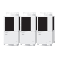
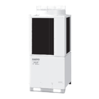
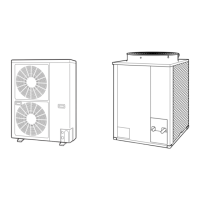
iii
Section 1: OUTLINE OF 3-WAY ECO-i SYSTEM ...................................................................1-1
1. Line-up .............................................................................................................1-2
2. Features of 3-WAY ECO-i SYSTEM ................................................................1-4
Section 2: DESIGN OF 3-WAY ECO-i SYSTEM .....................................................................2-1
1. Model Selecting and Capacity Calculator ........................................................2-2
2. System Design ...............................................................................................2-18
3. Electrical Wiring .............................................................................................2-24
4. Installation Instructions ..................................................................................2-30
Section 3: Control of 3-WAY ECO-i SYSTEM ........................................................................3-1
1. Main Operating Functions ................................................................................3-3
2. Wireless Remote Controller .............................................................................3-5
3. Timer Remote Controller................................................................................3-29
4. System Controller ..........................................................................................3-48
5. Schedule Timer ..............................................................................................3-70
6. Simplifi ed Remote Controller .........................................................................3-95
7. Remote Sensor ............................................................................................3-103
Section 4: 3-WAY ECO-i SYSTEM UNIT SPECIFICATIONS ..................................................4-1
1. Outdoor Unit ....................................................................................................4-3
2. 4-Way Air Discharge Semi-concealed Type (X, XM Types) ............................4-27
3. 2-Way Air Discharge Semi-concealed Type (S Type) .....................................4-84
4. 1-Way Air Discharge Semi-concealed Type (A Type) ...................................4-100
5. Wall-Mounted Type (K Type) ........................................................................4-109
6. Ceiling-Mounted Type (T Type) ....................................................................4-133
7. Concealed Duct Type (U, US Types) ............................................................4-162
8. Concealed Duct High Static Pressure Type (D Type) ...................................4-299
9. Floor-Standing Type (F Type) .......................................................................4-315
10. Concealed Floor-Standing Type (FM Type) ..................................................4-330
11. 1-Way Air Discharge Semi-concealed Slim Type (L Type) ...........................4-346
12. Total Heat Exchanger with DX coil (GU Type) ..............................................4-359
13. Intaking Fresh Air of Semi-Concealed Type and Concealed-Duct Type .......4-368
Section 5: TEST RUN ..............................................................................................................5-1
1. Preparing for Test Run .....................................................................................5-2
2. Test Run Procedure .........................................................................................5-3
3. Main Outdoor Unit PCB Setting .......................................................................5-4
4. Auto Address Setting .......................................................................................5-6
5. Remote Controller Test Run Settings .............................................................5-13
6. Caution for Pump Down .................................................................................5-13
7. Meaning of Alarm Messages .........................................................................5-14
Section 6: ELECTRICAL DATA ...............................................................................................6-1
1. Outdoor Unit ....................................................................................................6-2
2. Indoor Unit .......................................................................................................6-6
Section 7: PCB AND FUNCTIONS .........................................................................................7-1
1. Outdoor Unit Control PCB ...............................................................................7-2
2. Indoor Unit Control PCB Switches and Functions ...........................................7-6
Section 8: CAPACITY TABLE .................................................................................................8-1
1. Capacity Ratio of Outdoor Unit ........................................................................8-2
2. Cooling Capacity of Indoor Unit .....................................................................8-22
Contents
TD831143-00W-3WAY.indb4TD831143-00W-3WAY.indb4 2008/12/0110:25:312008/12/0110:25:31

 Loading...


