30 S4179544
33
33
3
X
Fig. 3-33
Fig. 3-34
Fig. 3-35
Hole-in-anchor
Hole-in-plug
Concrete Insert
Suspension bolt (M10 or 3/8")
(field supply)
0038_T_I
0057_S_I
A (ceiling opening dimension)
820 (ceiling opening dimension)
B (suspension bolt pitch)
Unit: mm
Refrigerant
tubing side
12
Electrical component box
Drain hose
side
590 (suspension bolt pitch)
12
1212
Length
Type
Type
Length
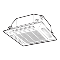
■ 4-Way Air Discharge Semi-Concealed Type
(X-Type)
3-9. Suspending the Indoor Unit
This unit uses a drain pump. Use a carpenter’s level to
check that the unit is level.
3-10. Preparation for Suspending
(1) Fix the suspension bolts securely in the ceiling
using the method shown in the diagrams (Figs.
3-33 and 3-34), by attaching them to the ceiling
support structure, or by any other method that
ensures that the unit will be securely and safely
suspended.
(2) Follow Fig. 3-34 and Table 3-2 to make the holes
in the ceiling.
Table 3-2 Unit : mm
AB
12,18, 25 820 730
36, 48 1110 1020
(3) Determine the pitch of the suspension bolts using
the supplied full-scale installation diagram. The
diagram and table (Fig. 3-35 and Table 3-3) show
the relationship between the positions of the
suspension fitting, the unit, and the panel.
Table 3-3 Unit: mm
ABCDE
12, 18, 25 150 200 255 298 125
36, 48 165 235 285 328 125
 Loading...