5.4 Connections Before starting up the unit; make sure that the unit is stable and secure.
Check all pneumatic and electrical connections on the unit.
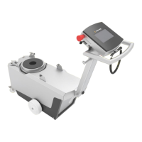
5.4.1 Front Panel and Back Panel The following displays are located on the front panel:
1 Standby
Is lit up when Sartocheck
®
4 plus Filter tester is ready for operations, but not
currently running any test program. (Blinking LED)
2 Ready
Lights up when the result of the filter test is ready. (LED lit)
3 Running
Is lit up when a test is currently running. (LED lit)
4 Error
Lights up when the test unit has identified an error and cancelled the test.
(LED lit)
The following connection ports are located on the back panel:
1 Housing ventilator
The unit is equipped with a ventilator that ensures that Sartocheck
®
4 plus
Filter tester is kept at a constant temperature.
2 Serial port MU (Management Unit)
This port is used for connecting accessories (e.g. barcode scanner).
3 AC adapter
Power plug for connecting the power cord to mains supply.
4 Fuses
Fine-wire fuses between unit and mains supply.
5 Network Connection
RJ45
5.4.2 Left and Right Panels
Sartocheck
®
4 plus Filter tester Located on the left panel:
1 Main power switch
Switch on the power with the main power switch.
2 SD Card Reader
The SD card reader is designed for standard SD cards for inputting and
storing data.
3 Serial port TU (test unit)
Port for connecting additional test units (Multiunits).
4 PLC Port
Port for connecting PLC controller signal input and output.
1 2 3 4
Fig. 5-2 | Front Panel
14
3
2
5
Fig. 5-3 | Back Panel
1 2 3 4
Fig. 5-4 | Left panel
Installation 17

 Loading...