Weigh Cell Operating Instructions 9
Device Description
11
10 9 6 4
3
8
1
2
1
7
5
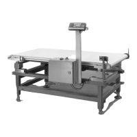
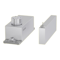
Fig. 3: WZB25-NC—View from the front (left) and rear (right)
Pos. Name Description
1 Pressure outlet
2 Rinsing run air outlet — Rinsing run air outlet < 50 mbar
— D = 6 mm
3 — For closing mechanism
— 6 bar
— D = 3 mm
4 Electrical connection To the electronics unit
5 Positioning hole 1 Is the anti-twist mechanism for the weigh cell.
6 Fixing thread
7 Mounting surface
8 Positioning hole 2 Is the anti-twist mechanism for the weigh cell.
9 Rinsing run air inlet — Rinsing run air inlet < 50 mbar
— D = 6 mm
10 — For internal motor weight unit
— 6 bar
— D = 3 mm
11 Retainer pin For customer-specific weighing pan
 Loading...