Do you have a question about the Savio GAIA 424 S and is the answer not in the manual?
Provides a labeled diagram of the boiler's front and rear views, identifying key components.
Illustrates the hydraulic circuits for central heating and domestic hot water operations.
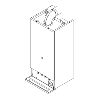
Lists and illustrates the main external panels of the boiler unit.
Provides instructions on how to safely remove the boiler's outer panels for access.
Details the procedure for accessing internal electrical components by removing the control panel cover.
Explains how to access the sealed combustion chamber by removing panels and covers.
Step-by-step guide to draining the central heating (C/H) water circuit.
Instructions for draining the domestic hot water (D.H.W.) circuit.
Presents a comprehensive wiring schematic of the boiler's electrical system, showing component connections.
Illustrates how the boiler operates under different conditions, showing electrical flow logic.
Describes the function and structure of the main heat exchanger, responsible for heat transfer.
Provides step-by-step instructions for removing the main heat exchanger from the boiler.
Details the procedure for cleaning the main heat exchanger, emphasizing care to avoid damage.
Explains the role of the D.H.W. heat exchanger in transferring heat to domestic hot water.
Outlines the process for removing the D.H.W. heat exchanger, including safety precautions.
Describes the pump's function in circulating water through the heating and D.H.W. systems.
Details checks for pump operation, seized motor, and electrical resistance.
Provides instructions for safely removing the pump from the boiler.
Explains the diverter valve's role in switching water flow and its interaction with the D.H.W. pressure switch.
Guides on checking the general operation of the diverter valve and D.H.W. pressure switch.
Provides steps for removing the diverter valve and its related components.
Describes the primary role of the electronic control circuit in managing boiler operations based on external inputs.
Identifies various selection and adjustment devices located on the control circuit board.
Explains how the control circuit manages temperature regulation using probes and user settings.
Details the function of microswitches used to select boiler operating modes and gas types.
Explains how to adjust gas pressure for the injectors during the ignition phase.
Describes how to limit the maximum output power for the central heating function.
Covers checks for the fuse and general circuit operation.
Provides step-by-step instructions for safely removing the electronic control circuit board.
Illustrates the thermal control logic for heating when the function switch is in the '•' mode.
Details the thermal control logic for heating when the function switch is in the '*' mode.
Explains the purpose of the PCB that displays operational information via LEDs.
Details the function and color indications of the various LEDs on the display circuit.
Guides on safely removing the display circuit board.
Describes the role of the ignition device in managing the ignition sequence and flame detection.
Covers checks related to the shutdown sequence and burner ignition.
Provides step-by-step instructions for safely removing the ignition device.
Presents a flowchart detailing the sequence of operations for burner ignition.
Explains how the gas valve controls gas inflow to the burner for on-off and modulation.
Lists and illustrates the different parts of the gas valve.
Details the procedure for adjusting minimum and maximum gas pressure at the burner.
Covers checks for the modulating operator coil and electrical resistance of on-off operators.
Provides instructions for safely removing the gas valve assembly.
Explains the flow switch's role in controlling pump operation and water presence.
Guides on checking the switch's mechanical function and electrical operation.
Provides steps for safely removing the main circuit flow switch.
Describes the D.H.W. filter's purpose in stopping impurities in the return circuit.
Details the procedure for safely removing the D.H.W. filter.
Explains the function and installation of flow limiters for D.H.W. flow rate.
Explains how temperature probes convert water temperature into electrical signals.
Guides on checking probe function by measuring resistance against temperature.
Provides instructions for safely removing temperature probes.
Describes the by-pass valve's function in ensuring minimum flow across the heat exchanger.
Outlines the procedure for safely removing the by-pass valve.
Explains the function of water pressure switches in indicating water pressure and controlling the pump.
Guides on checking the operating points and contacts of the pressure switches.
Provides steps for safely removing a water pressure switch.
Details how to access and remove the pump relay.
Describes the fan's role in expelling combustion products and its control system.
Covers checks for the fan motor resistance and air pressure switch operation.
Provides instructions for safely removing the boiler fan.
Guides on safely removing the air pressure switch.
Explains the role of ignition and detection electrodes in the burner ignition sequence.
Guides on checking electrode position and connection integrity.
Provides steps for safely removing ignition and detection electrodes.
Describes the safety thermostat's function to prevent overheating by stopping the ignition device.
Covers checks for probe integrity, capillary connection, and overheat temperature value.
Provides instructions for safely removing the safety thermostat switch.
| Max Working Pressure | 3 bar |
|---|---|
| Mounting | Wall-mounted |
| Combustion Type | Sealed |
| Fuel Type | Natural Gas or LPG |
| Ignition Type | Electronic |