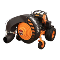
Do you have a question about the Scag Power Equipment Windstorm WS23-37BV-EFI and is the answer not in the manual?
| Brand | Scag Power Equipment |
|---|---|
| Model | Windstorm WS23-37BV-EFI |
| Category | Blower |
| Language | English |
Provides an overview of the blower and the importance of following manual instructions.
Defines terms like "Right", "Left", "Front", and "Rear" relative to machine orientation.
Clarifies that detailed engine/transmission repair is not covered, directing users to dealers.
Explains the meaning of various symbols used throughout the manual for clarity.
Emphasizes operator safety, responsibility, and the necessity of proper training and manual comprehension.
Explains the meaning and significance of hazard signal words (DANGER, WARNING, CAUTION) and symbols.
Details essential checks and precautions to take before starting the blower, including safety rules.
Provides step-by-step instructions to verify the correct operation of the machine's safety interlock system.
Offers vital safety guidelines and best practices for operating the blower effectively and avoiding hazards.
Covers crucial safety practices for maintenance tasks and guidelines for proper equipment storage.
Explains spark arrestor requirements and relevant regulations, particularly for certain environments.
Notes compliance of the spark ignition system with Canadian standards (ICES-002).
Illustrates and explains the purpose of various safety and instructional decals found on the equipment.
Details the engine model, displacement, type, fuel system, and other technical specifications.
Outlines specifications for the battery, charging system, and electrical components like switches and gauges.
Covers specifications for the drive system, hydraulic pumps, steering, wheels, and fuel tank capacity.
Provides performance specifications for the blower, including impeller size, blade count, and CFM ratings.
Lists the overall dimensions (length, width, height) and operating weight of the machine.
Explains the function of each indicator light on the Tiger Eye monitoring system for operational feedback.
Details the location and function of all major controls and switches on the operator panel.
Explains the purpose and function of the safety interlock system designed to prevent accidental operation.
Provides step-by-step procedures to verify the correct operation of the safety interlock system before use.
Outlines the necessary checks and procedures for the first 20 hours of operation to ensure proper break-in.
Guides the user through the process of starting the engine, including important cautions and pre-start checks.
Explains how to operate the machine's movement controls for forward, reverse, and steering maneuvers.
Details the procedure for engaging the blower fan drive, including notes on soft start operation.
Provides critical safety guidelines and operational techniques for safely handling the machine on slopes.
Outlines the correct procedure for safely parking the machine on level surfaces.
Describes essential post-operation tasks, including cleaning, checks, and safe refueling practices.
Details safe procedures for clearing blockages from the air intake or discharge nozzle.
Explains how to manually move the machine when the engine is not running (free-wheeling).
Offers practical advice and tips for optimizing blowing performance and ensuring safety during operation.
Explains how to adjust the nozzle's vertical tilt and horizontal direction for optimal air stream control.
Provides instructions to adjust the parking brake for proper engagement and holding power.
Covers adjustments for neutral tracking and steering alignment to ensure the machine travels straight.
Notes that throttle and choke adjustments are typically performed by an authorized dealer.
Addresses belt inspection, alignment, and potential issues like wear or breakage.
Emphasizes the importance of correct belt alignment for proper blower performance and to prevent premature wear.
Details the procedure for adjusting the electric clutch air gap for correct operation and longevity.
Explains how to remove the operator cushion and rear cover to access internal components for maintenance.
Provides a comprehensive schedule of maintenance tasks and recommended service intervals based on operating hours.
Details the lubrication schedule, specifying locations, intervals, and recommended lubricants for fittings.
Covers procedures for checking hydraulic oil levels and changing hydraulic oil and filter elements.
Explains how to check the engine oil level and outlines the procedure for changing engine oil and the oil filter.
Details procedures for filling the fuel tank, specifying fuel types, and emphasizing gasoline handling safety.
Describes the process for cleaning or replacing the engine's air cleaner element to maintain performance.
Provides safety precautions and instructions related to the battery, including charging and handling.
Outlines the recommended checks for drive belts, including alignment, wear, and tensioning.
Advises on the frequency of checking tire pressures for optimal performance and safety.
Covers recommended procedures for cleaning, repairing minor damage, and waxing the machine's body and blower.
Details the procedures for checking and changing the lubricant in the blower drive gearbox.
Lists optional attachments and accessories that are approved for use with the Scag blower.
Shows an exploded view of the impeller drive assembly, identifying all component parts.
Displays an exploded view of the impeller assembly, detailing all its constituent parts.
Provides an exploded view of the machine's sheet metal components and their part numbers.
Illustrates the components of the machine's steering system, including linkages and controls.
Depicts an exploded view of the fuel system, showing the tank, lines, filter, and related components.
Shows an exploded view of the hydraulic system and engine components, identifying individual parts.
Illustrates the components of the machine's electrical system, including wiring, switches, and gauges.
Details the parts diagram for the electrical system controlling the nozzle direction and tilt functions.
Displays an exploded view of the hydraulic pump, identifying its internal parts and kits.
Lists and shows the various decals and information plates used on the machine for safety and identification.
Provides the detailed wiring diagram for the machine's electrical system, essential for troubleshooting.
Details the wiring harness assembly for the nozzle control system, showing connections and wire colors.
Shows the components related to the soft start module, including the module itself and its connections.
Details the engine adapter harness assembly, showing its connections to the main harness and the engine.
 Loading...