Schaffner International Ltd
Sine Wave Filter FN 5040 / FN 5045 / FN5040HV
Mounting and Installation Guidelines
INS 112882 G 2I3
The pictures above show permitted and prohibited mounting positions. The mounting on a vertical plate
(top left picture) is limited to IP00 products with a maximum weight of 25 kg or for IP20 products of
FN 5045 series (far right picture) up to 115 A. Use all available mounting holes and select the correct
screws and washers in order to ensure a reliable mounting and to do justice to the weight of these products.
Apply torques appropriate for the strength class of the screws and washers you are using. Specifications
can be obtained from the supplier of the screws and washers.
Wiring and connections
The filter rating has to be compatible with the drive rating. All drives manufacturer installation and safety
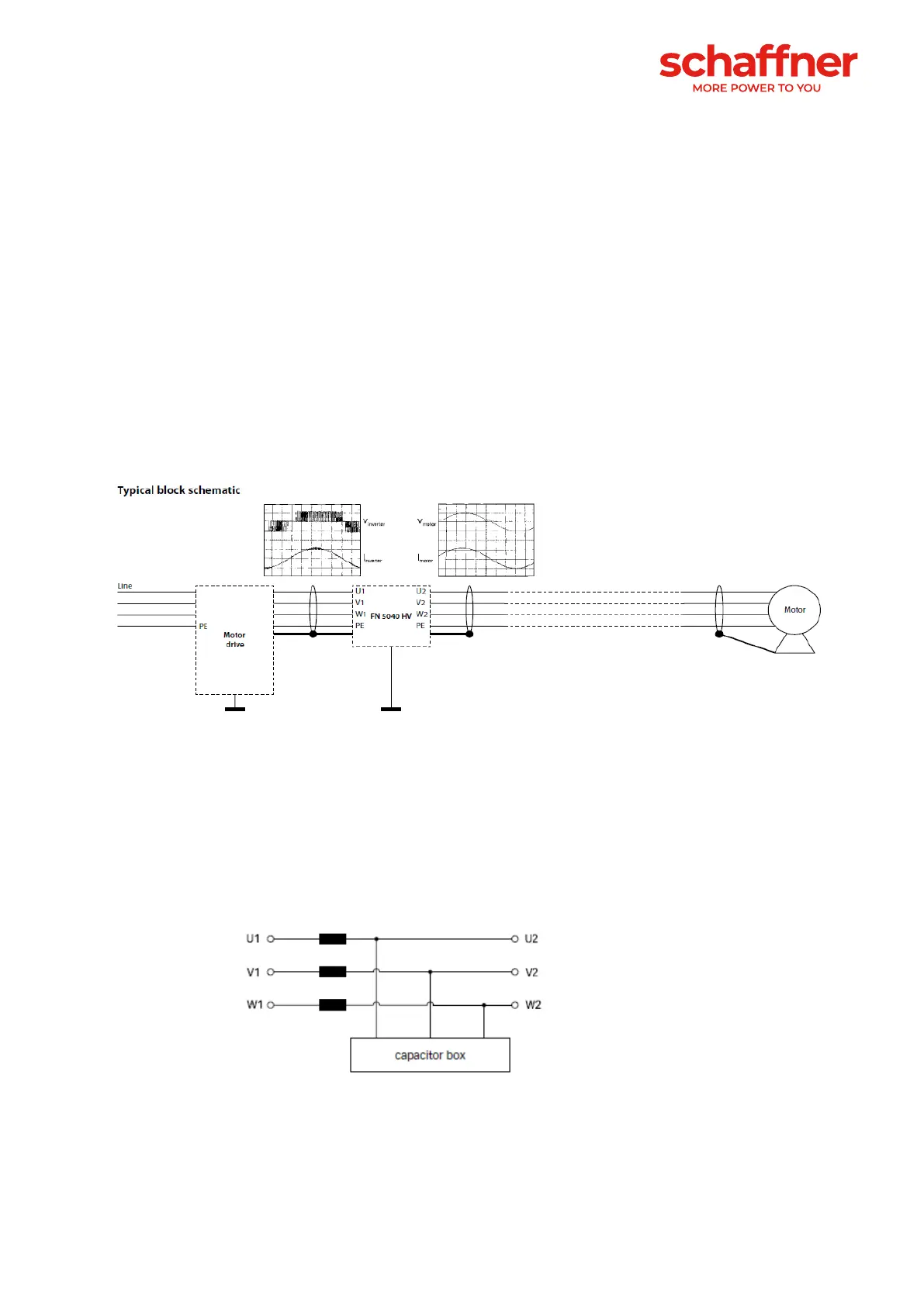
instructions must be fulfilled. The typical block schematic is shown for a motor load, but the load can be
also multiple motors or a transformer. Drives and load cable selection/placement should be in accordance
with all local electrical standards and regulations.
Use 75°C Copper Conductors only.
In many applications a shielded motor cable may not be required when a sine wave filter is applied with a
motor drive. Anyhow, due to other possible influences of common mode disturbances Schaffner does
recommend to use shielded motor cables. This is to avoid back-coupling of radiated interferences to the
mains cable at the frequency range from 1–30 MHz. This EMC measure however can only be considered
to be efficient, if the ends of the cable shield of the motor cable are put in proper HF low-impedance contact
with the ground of the motor and the frequency converter.
Sine wave filters with separate capacitor bank must be connected as follows:
Drive Motor
 Loading...