4. COLLEGAMENTI ELETTRICI / WIRING CONNECTION
6. DIMENSIONI INGOMBRO / OVERALL DIMENSIONS
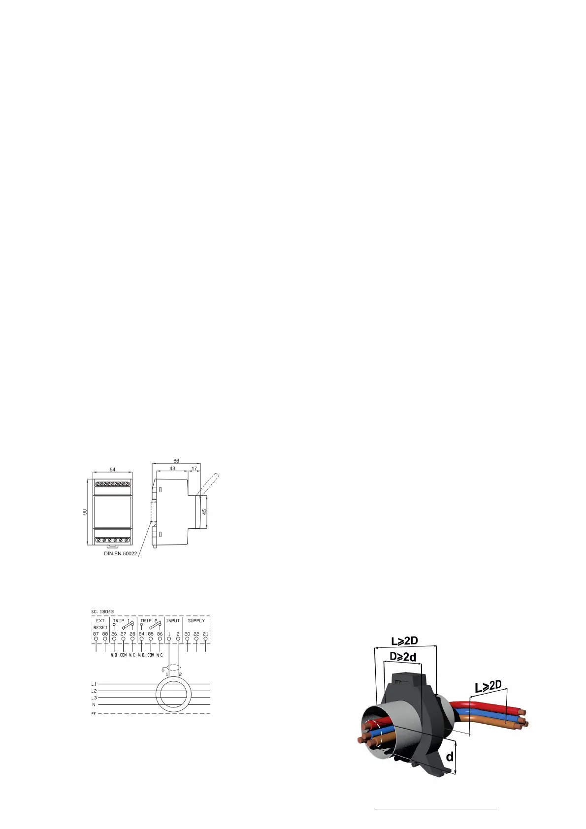
7. SCHEMI DI INSERZIONE / WIRING DIAGRAMS
Per il collegamento seguire lo schema di inserzione. Di seguito si descrivono i diversi punti riguardanti le diverse
connessioni elettriche.
NOTA: Tu tti i co lleg am ent i de vo no ess er e tenuti i l pi ù co rti possibile; La massima lunghezza raccomandata è di 3 metri
Collegamento Toroide
Collegare i morsetti 1 e 2 con i morsetti di uscita del trasformatore toroidale SCHALT cod.TDN… utilizzando un
cavo twistato e schermato (tipo Belden 9841 o similare) e collegando esclusivamente una sola estremità dello
schermo alla terra dell’impianto.
NOTA: Il percorso dei cavi di collegamento del toroide deve essere separato dai cavi di alta corrente, alta tensione
e da cavi che comandano elementi induttivi come teleruttori, ecc. Se sono posati nella stessa canalina metallica
usare opportuni separatori.
Collegamento uscite relè
Le uscite sono costituite da uno o due relè con un contatto di scambio ciascuno.
I due relè di intervento (TRIP) commutano contemporaneamente quando si è raggiunto il limite di corrente e
tempo pressato per l’intervento o quando si verica un guasto del collegamento con il toroide.
NOTA: Utilizzando i contatti per pilotare carichi induttivi (bobine a relè, teleruttori, solenoidi) è necessario
limitare la sovratensione che sistematicamente si verica ai capi dell’induttore in corrispondenza di ogni apertura
del contatto, inserendo: un gruppo R/C in parallelo all’induttore, se questo lavora in alternata, o un diodo in
antiparallelo se l’induttore lavora in continua. All’interno i relè sono isolati a 4kV tra i contatti e la bobina.
Ripristino a distanza
Collegare un contatto in chiusura ai morsetti RESET per eseguire il reset manuale a distanza.
In order to do all the connections, follow the diagram. The following points will explain in more detail.
NOTE: All the connections must be kept as short as possible; The recommended maximum length is 3 meters
CT Connection
The terminal blocks 1 and 2 should be connected to the measuring windings of the CT SCHALT code TN… by a
twisted and shielded pair cable (type Belden 9841 or similar); the shlield must be connected to the system ground at
one end only.
NOTE: The CT wiring should be placed away from high current and voltage conductors or sources of strong magnetic
elds, to minimize noise pickup and interference on the relay. If the wires have only one route, separate the wires
with some metallic element.
Output contacts connections
The outputs consist of one or two mechanical relays with one changeover contact.
The two (2) TRIP relays will activate when the earth leakage current overcome the trip threshold for the specied
delay time or CT wiring interruption occurs.
NOTE: Using the contacts for control of inductive loads in Vac (coils of relays, contactors, solenoids), it’s necessary
to limit the over voltage connecting a R/C group in parallel to the inductor. If it works in DC, a diode in anti-parallel
should be connected. The internal relays are isolated 4 kV between contact and coil.
Remote Reset
It is possible to execute the remote manual reset by a closing contact connected to RESET terminals.
CABLAGGIO CONSIGLIATO - SUGGESTED WIRING
Vengono di seguito spiegati il funzionamento e la programmazione dei parametri di intervento e ripristino dello
strumento.
LED “ON”: (verde) indica la presenza della tensione ausiliaria.
LED “TRIP”: (rosso) il led “TRIP” acceso indica che la corrente attraverso il toroide ha superato la soglia TRIP
impostata per il tempo programmato. I corrispondenti relè sono scattati comandando lo sgancio dell’interruttore
generale.
PULSANTE “RESET”: questo pulsante si usa per il ripristino manuale dello strumento da un intervento (se sono
state ripristinate le condizioni precedenti l’intervento).
PULSANTE “TEST”: Consente di fare una prova di funzionamento dei relè.
NOTA: Fare attenzione al carico collegato ai relè di uscita. Premendo il pulsante i relè commuteranno e resteran-
no commutati no a che non verrà premuto il pulsante “RESET”.
Programmazione del valore della corrente di intervento
Si sceglie il campo della corrente di intervento desiderata posizionando i primi due microinterruttori (partendo
dall’alto):
• Entrambi su IΔnx0,1: 30÷300mA
• Solo il primo su IΔnx1 (il secondo resta posizionato su IΔnx0,1): 300mA÷3A
• Solo il secondo su IΔnx1 (il primo resta posizionato su IΔnx0,1): 3÷30A
Si imposta il valore di corrente agendo sul trimmer IΔn(A)
Programmazione del tempo di ritardo dell’intervento
Si sceglie il campo del tempo di intervento desiderato posizionando il terzo microinterruttore:
• Δtx1 : istantaneo÷0,5s
• Δtx10 : 0,2÷5s
Si imposta il valore del tempo agendo sul trimmer Δt(s)
Programmazione del modo operativo dei contatti
Posizionando il quinto microinterruttore si può impostare il tipo di sicurezza:
ND (normale) o NE (positiva).
Programmazione del tipo di ripristino
Il ripristino dello strumento dopo un intervento può avvenire in modo Manuale o Automatico. Quando il ripristino
è manuale si può eettuare in maniera Locale premendo il tasto RESET o in maniera Esterna tramite un pulsante
esterno collegato ai morsetti RESET (87-88).
Si sceglie il tipo di ripristino posizionando il sesto microinterruttore:
MAN (ripristino manuale) o AUTO (ripristino automatico)
NOTA: Il ripristino Automatico è possibile solo quando il valore di corrente dierenziale rilevato scende al di sotto
del 90% del valore di corrente impostato.
Operation and setting about Trip and Reset are explained as follows.
LED “ON”: (green) indicates that the instrument is supplied.
LED “TRIP”: (red) the led “TRIP” turned on shows that the current through the CT has risen above the trip setpoint and
the programmed trip time. The trip contact has tripped the circuit breaker.
“RESET” PUSH-BUTTON: this push-button is used to reset from a fault condition.
“TEST” PUSH-BUTTON: this push-button allows to do the contacts test.
NOTE: Be careful to the load connected to the output contacts. If the push-button is pressed, the output contacts will
actuate and will stay on that position until the “RESET” push-button is pressed.
Trip current setting
The selection of the trip current range is done switching the two above microswitch:
• Both on IΔnx0,1: 30÷300mA
• The rst on IΔnx1 (the second remains on IΔnx0,1): 300mA÷3A
• The second on IΔnx1 (il primo resta posizionato su IΔnx0,1): 3÷30A
Set the Trip Current by the trimmer IΔn(A).
Trip delay time setting
The selection of the trip delay time range is done switching the third microswitch:
• Δtx1: instantaneous÷0,5s
• Δtx10: 0,2÷5s
Set the Delay Time by the trimmer Δt(s)
Operating mode of the trip contacts
The selection of the safety operating mode of the trip contacts is done by switching the fth microswitch:
ND (normal) or NE (positive)
Reset mode setting
The reset of the instrument from a fault condition is possible in Manual or Automatic mode. In Manual mode the reset can
be Local (pressing the push-button RESET) or Remote (by a push-button connected to the RESET terminals 87-88).
The selection of the reset mode is done switching the sixth microswitch: MAN (manual reset) or AUTO (automatic reset).
NOTE: Automatic reset is possible only when the leakage current falls below a 90% of set trip current.
5. FUNZIONAMENTO / FUNCTIONS
Kg 0,25
 Loading...