37
2021-04-12 / V1.1
Contactors CP Series – Installation and Maintenance Instructions
Maintenance
On the left hand side:
X
Position the new auxiliary switch assembly (6) and
connect the actuating arm to the shaft (7).
X
Screw in the 2 xing screws (5).
X
Tighten the 2 xing screws (5) to a torque of
1.5Nm.
X
Install the shaft circlip (4) in the groove on the
shaft (7).
On both sides (right and left):
X
Reconnect the control wires to the auxiliary switch-
es, see “8.4.6 Connecting the main contacts”.
9.3.6 Replacing the optional
pre-charging contactor (CPP)
A separate installation and maintenance
manual is available for CPP contactors.
Also refer to this separate manual C45-m.
Available for download at: https://www.
schaltbau.com/en/media-library/
Safety
DANGER
Before beginning any work on the contac-
tors, make sure that
X
there is no voltage present,
X
all safety regulations are fully ob-
served.
X
Refer also to section „Dangers and
security measures“ on page 6.
Spare parts required
Pre-charging contactor (CPP), see chapter “10. Spare
parts”
Tools required
- Set of torx bits
- Torque wrench
Preliminaries
- The CP main contactor is completely dismounted
from the mounting frame or plate, see “8.2 Mechani-
cal installation”.
- The cables at the pre-charging contactor (CPP) are
disconnected, see “8.4.8 Connecting the optional
pre-charging contactor (CPP)”.
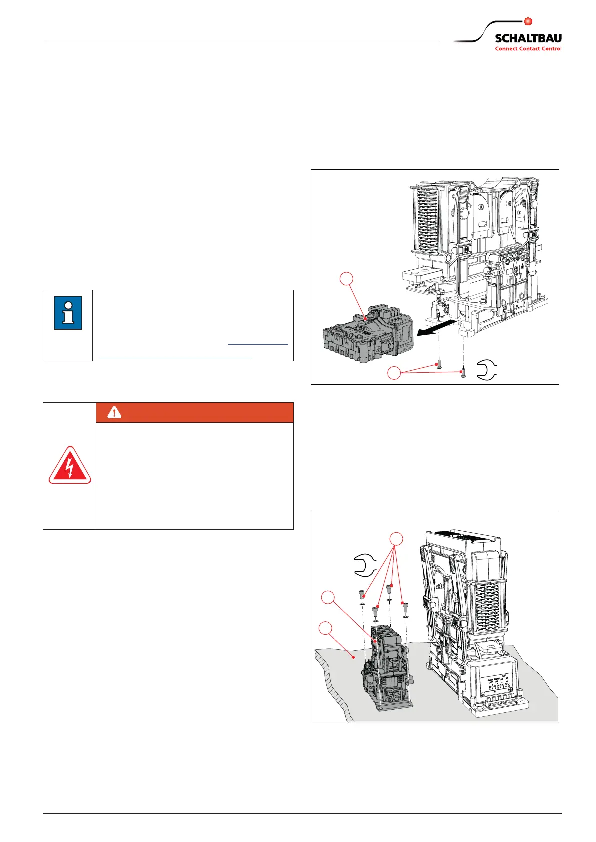
Removing the pre-charging contactor
(CPP)
With 1,200 A and 2,000 A devices
X
Unscrew the 2 mounting screws (2).
X
Remove the CPP (1).
2
4
Nm
1
Fig. 41: With 1,200 A and 2,000 A devices: Replace the pre-
charging contactor (CPP) mounted on the base plate
of the main contactor
With 600 A devices
X
Unscrew the 4 mounting screws (2) on the mount-
ing ange of the CPP (1).
X
Remove the CPP (1).
3
2
Nm
1
Fig. 42: With 600 A devices: Replace the pre-charging
contactor (CPP) mounted at a separate mounting po-
sition next to the main contactor
 Loading...