23
2019-03-06 / V1.0
Contactors CT/CU Series – Installation and Maintenance Instructions
Installation
Electrical installation procedure
Electrical connection of the auxiliary switches
Depending on the contactor type, see Fig. 13 to Fig. 16.
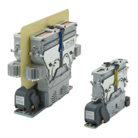
The auxiliary switches of contactors with
plug and socket connectors are com-
pletely wired when shipped from the
factory (see gure Fig. 15 (7)). Electrical
connection of the auxiliary switches is not
necessary for these contactor types.
Preconditions:
- The upper module is removed.
- The protection cap of the auxiliary switches is re-
moved (except for contactor types with plug and
socket connectors).
X
Connect the wires (2) to the terminals of the auxil-
iary contacts (1).
- For the a1 and b0 contacts (Snap action switch-
es S870) no polarity must be observed.
- For the general purpose contacts (Snap action
switches S826) the polarity must be observed.
The position of the switches and the terminal
numbers are shown on a label on the protec-
tion cap.
1
2
Fig. 13: CT/CU 1115/04, 1130/04, 1115/08, 1130/08:
Connect the wires (2) to the terminals of the auxiliary
contacts (1)
1
2
Fig. 14: CT/CU 1215/04, 1230/04, 1215/08, 1230/08:
Connect the wires (2) to the terminals of the auxiliary
contacts (1)
7
Fig. 15: CT/CU 1115/10/11, 1130/10/11: Auxiliary switches
of contactors with plug and socket connectors are
completely wired when shipped from the factory (7).
Electrical connection of the auxiliary switches is not
necessary for these contactor types.
1
2
Fig. 16: CT/CU 1215/10/11, 1230/10/11: Connect the wires (2)
to the terminals of the auxiliary contacts (1)
Electrical connection of the coil control wires
Depending on the contactor type, see Fig. 17 to Fig. 20 .
Preconditions:
- The upper module is removed.
- The protection cap for the coil controller terminals is
removed.
X
Connect the coil control wires (4) to the cage
clamp terminals (3).
X
For contactor types with plug and socket connec-
tors, connect the plug to the socket (7).
3
4
Fig. 17: CT/CU 1115/04, 1130/04, 1115/08, 1130/08:
Connect the coil control wires (4) to the cage clamp
terminals (3).
 Loading...