41
2019-03-06 / V1.0
Contactors CT/CU Series – Installation and Maintenance Instructions
Maintenance
Replace the auxiliary switches
If the auxiliary switches have to be replaced all switches
of one type (S826 or S870) must be replaced.
Required tools and auxiliaries
- Socket wrench set
- Set of hexagon socket wrenches
- Set of POZIDRIV® cruciform screwdrivers
- Set of slotted screwdrivers
- 90° angle gauge
Preconditions
- The main cables/busbars are removed.
- The upper module is removed.
- The protection cap for the auxiliary switches is re-
moved.
- The wires of the auxiliary switches are disconnected.
For detailed instructions about the above listed precon-
ditions refer to section “9. Installation”.
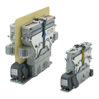
Remove the auxiliary switch subassembly
Depending on the contactor type, see Fig. 72 to Fig. 75.
(The actual version may dier from the gures. Stand-
ard versions are either 4x S826 or 2x S826 + 2x S870
switches)
X
Note the mounting position of the subassembly
and the individual switches.
X
Remove the 2 knurled thumb screws (1) including
washers.
X
Remove the 2 hexagon socket head screws (2) in-
cluding washers.
2
1
2
1
Fig. 72: CT/CU 1115/04, 1130/04, 1115/08, 1130/08,
1115/10/11, 1130/10/11: Remove the auxiliary switch
assembly 1
2
1
2
1
Fig. 73: CT/CU 1215/04, 1230/04, 1215/08, 1230/08,
1215/10/11, 1230/10/11: Remove the auxiliary switch
assembly 1
X
Pull the subassembly (3) sideways out in the direc-
tion as shown in the gures below.
3
5
4
Fig. 74: CT/CU 1115/04, 1130/04, 1115/08,
1130/08,1115/10/11, 1130/10/11: Remove the
auxiliary switch assembly 2
3
5
4
Fig. 75: CT/CU 1215/04, 1230/04, 1215/08, 1230/08,
1215/10/11, 1230/10/11: Remove the auxiliary switch
assembly 2
 Loading...