42
2019-03-06 / V1.0
Maintenance
Contactors CT/CU Series – Installation and Maintenance Instructions
X
Dismount the S826 switches (4) and/or the S870
switch assembly (5) one by one to avoid wrong re-
mounting.
X
If all switches are removed together
and remounted again a readjust-
ment of the frame is necessary. Refer
to Fig. 78.
Remove the S870 switch assembly
X
Remove the 2 screws (6) including washers on
the top of the frame using a POZIDRIV® cruciform
screw driver size 1.
X
Keep the screws and washers in a safe place.
X
Remove the entire S870 switch assembly (5).
5
6
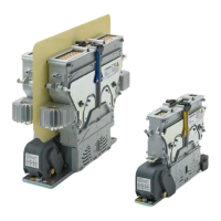
Fig. 76: CT/CU 1115/04, 1130/04, 1115/08, 1130/08, 1215/04,
1230/04, 1215/08, 1230/08, 1115/10/11, 1130/10/11,
1215/10/11, 1230/10/11: Remove the snap action
switch assembly S870
Remove the S826 snap action switches
X
Remove the 2 screws (7) including washers for
each switch on the bottom of the frame using an
appropriate POZIDRIV® cruciform screw driver.
X
Keep the screws and washers in a safe place.
7
4
Fig. 77: CT/CU 1115/04, 1130/04, 1115/08, 1130/08, 1215/04,
1230/04, 1215/08, 1230/08, 1115/10/11, 1130/10/11,
1215/10/11, 1230/10/11: Remove snap action switch-
es S826
Install a new S870 switch assembly
X
Install the new S870 switch assembly with the
2 screws (6) including washers on the top of the
frame using a POZIDRIV® cruciform screw driver
size 1.
X
Tighten the 2 screws (6) with a torque of 1 Nm.
X
Check that all replaced parts are properly in place
and xed tightly.
Install new S826 snap action switches
X
Install the the new switches with the 2 screws (7)
including washers for each switch on the bottom
of the frame using an appropriate POZIDRIV® cru-
ciform screw driver.
X
Tighten the 2 screws (7) with a torque of 1 Nm.
X
Check that all replaced parts are properly in place
and xed tightly.
 Loading...