44
2019-03-06 / V1.0
Maintenance
Contactors CT/CU Series – Installation and Maintenance Instructions
2
1
2
1
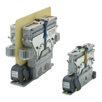
Fig. 82: CT/CU 1215/04, 1230/04, 1215/08, 1230/08,
1215/10/11, 1230/10/11: Re-install the auxiliary
switch assembly 2
Re-install the contactor
X
Connect the wires of the auxiliary switches.
X
Install the protection caps for the auxiliary switch-
es.
X
Install the upper module to the lower module and
lock the upper module securely.
X
Reconnect the main cables/busbars.
For detailed instructions about the above listed re-in-
stallation procedures refer to section “9. Installation”.
Checks
After the maintenance work is completed, do the fol-
lowing checks:
X
Check the protective earth.
X
Check the main connections.
X
Check the control connections.
X
Check the latching and locking between upper
and lower module.
X
Check that both protection covers are tted.
X
Perform several activation and deactivation op-
erations of the contactor without the main circuit
active.
X
Check the function of the auxiliary switches:
Use a continuity tester to check that the wiring is
correct and the auxiliary switches are functioning
correctly.
X
Check the pull-in voltage and drop-o voltage
according to the requirements of Schaltbau.
X
After each installation and after replacement of
main contacts, contact bridge or after any other
modications, alterations or maintenance works,
always perform complete checks according to
these standards:
- IEC 60077-2
- IEC 60947-4-1
 Loading...