13
2019-03-06 / V1.0
Contactors CT/CU Series – Installation and Maintenance Instructions
Description
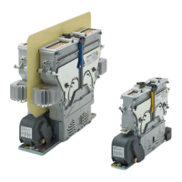
5.2 Parts description
Single pole contactors
CT/CU 1115/04, 1130/04 CT/CU 1115/08/10, 1130/08/10 CT/CU1115/11, 1130/11
A
B
3
4
5
6
789
10
1
A
B
3
4
5
6
8
9
10
1
7
A
B
3
4
5
6
8
9
10
11
7
12
A Upper module
1 Fixed contact with main terminals
3 Lock bars
4 Arc chute
5 Latching levers
11 Fixed contact with main terminal and heat sink
B Lower module
6 Auxiliary contact group with protection cap
7 Base plate
8 Magnetic drive with coil controller and moving con-
tact bridge (coil controller and moving contact bridge
are not visible in the gure)
9 Moving contact bridge (not visible in the gure)
10 Coil terminal group with protection cap
12 Double coil controller
Double pole contactors
CT/CU 1215/04, 1230/04 CT/CU 1215/08/10, 1230/08/10 CT/CU 1215/11, 1230/11
A
B
3
2
4
5
6
8
9
7
1
10
A
B
3
2
4
5
6
8
9
7
1
10
A
B
3
2
4
5
6
8
9
7
11
10
A Upper module
1 Fixed contact with main terminals
2 Insulation plate
3 Lock bars
4 Arc chute
5 Latching levers
11 Fixed contact with main terminal and heat sink
B Lower module
6 Auxiliary contact group with protection cap
7 Base plate
8 Magnetic drive with coil controller and moving con-
tact bridge (coil controller and moving contact bridge
are not visible in the gure)
9 Moving contact bridge (not visible in the gure)
10 Coil terminal group with protection cap
 Loading...