20
2019-03-06 / V1.0
Installation
Contactors CT/CU Series – Installation and Maintenance Instructions
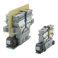
Remove the protection caps
Depending on the contactor type, see Fig. 9 to Fig. 12.
X
Remove the both protection caps (3 + 4).
- Remove the both knurled thumb screws (5) in-
cluding washers and remove the protection cap
for the auxiliary switches (3).
- Unscrew the slotted-head screw (6) including
washers and remove the protection cap for the
coil terminal (4).
5
3
6
4
Fig. 9: CT/CU 1115/04, 1130/04, 1115/08, 1130/08:
Remove the protection cap (3) of the auxiliary switch-
es and the protection cap (4) of the coil terminal
5
3
6
4
Fig. 10: CT/CU 1215/04, 1230/04, 1215/08, 1230/08:
Remove the protection cap (3) of the auxiliary switch-
es and the protection cap (4) of the coil terminal
3 6
4
5
Fig. 11: CT/CU 1115/10/11, 1130/10/11: Remove the protec-
tion cap (3) of the auxiliary switches and the protec-
tion cap (4) of the coil terminal
5
3
4
6
Fig. 12: CT/CU 1215/10/11, 1230/10/11: Remove the protec-
tion cap (3) of the auxiliary switches and the protec-
tion cap (4) of the coil terminal
Mount the lower module to the mounting frame or
plate.
Depending on the colour of the lock bars (yellow, red,
blue), the contactors must be be installed either in hori-
zontal or vertical position. Refer to chapter “8. Correct
mounting positions”.
X
Clean the surface of the mounting frame or plate.
X
Clean the base plate at the lower module of the
contactor.
X
Place the lower module on the prepared mount-
ing frame or plate.
X
Fix the lower module with the appropriate screws
and screw locking elements (and nuts if applica-
ble). Schaltbau strongly recommends Schnorr-
Washers (or similar) to secure the screws.
X
Thighten the screws with the correct torque that is
required for the used screws.
9.3 Electrical Installation
Preliminaries
X
Observe the minimum clearance of live parts to
the arc chute! Refer to the dimension drawings in
our catalogues C20.en (for single pole contactors)
and C21.en (for double pole contactors).
X
Switching electrical currents at high voltages will
produce arcing and plasma may exit out of the arc
chambers. It is essential to observe the minimum
clearance to earth and to the connecting bus bars
to avoid the risk of a ash-over. The minimum
clearance has been tested and specied in relation
to the switching capacity of the contactors.
X
For switching heavy loads allow a minimum time
of 30 s between switchings. Allow a recovery time
of at least 10 min after 3 heavy load switchings in
succession.
 Loading...