21
2019-03-06 / V1.0
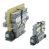
Contactors CT/CU Series – Installation and Maintenance Instructions
Installation
X
Ensure sucient ventilation, especially in the case
of heavy arc switching. Allow the exchange of sur-
rounding atmosphere to avoid the risk of ash-
overs and excessive corrosion.
X
The minimum gauges for the main terminals and
the earth terminal must be observed. Schaltbau
strongly recommends busbars for the connection
of the main terminals. The required cross sections
of the busbars depend on the contactor type and
are shown in the following table:
Contactor type CT/CU Required
cross section
of busbars
Single pole
contactors
1115/04 1130/04 40 x 4 mm
1115/08 1130/08 80 x 8 mm
1115/10/11 1130/10/11 80 x 10 mm
Double pole
contactors
1215/04 1230/04 40 x 4 mm
1215/08 1230/08 80 x 8 mm
1215/10/11 1230/10/11 80 x 10 mm
X
If wires are used the wire gauges must be selected
in coordination with their insulation class and the
operating conditions.
X
Undersized gauges for the earth terminal may pro-
duce a safety hazard.
X
Refer to catalogues for the power consumption of
the magnetic drive system and the electrical data
of the auxiliary switches:
- C20 (Catalogue for Contactors CT/CU 1115/04,
1130/04, 1115/08 and 1130/08)
- C21 (Catalogue for Contactors CT/CU 1215/04,
1230/04, 1215/08 and 1230/08)
- D26 (Catalogue for Snap Action Switches S826)
- D70 (Catalogue for Snap Action Switches S870)
The following information concerns only the contactor
types:
- CT 1215/08 and 1230/08
- CT 1115/10/11 and 1130/10/11
- CT 1215/10/11 and 1230/10/11
The magnetic drive system has 2 coils: 1 low resistance
pull-in coil and a high-resistance coil. During the pull-
in operation the high-resistance coil is short-circuited
allowing for a high pull-in power. After approximately
1 s the short circuit is released and both coils are con-
nected in series. The pull-in and holding operation is
controlled automatically by an internal controller. The
driving circuit however must be capable of supplying
the pull-in power for approx. 1 s.
- High pull-in power operation (approx. 230 W for 1 s;
U
s
= U
s n
; T
a
= 20 °C)
- Low power holding operation (< 30 W; U
s
= U
s n
;
T
a
= 20 °C)
- Overvoltage limitation
The high pull-in power allows stronger return springs
reducing the danger of contact welding during making
and breaking signicantly.
The low holding power reduces power consumption
without loss of performance
 Loading...