43
2019-03-06 / V1.0
Contactors CT/CU Series – Installation and Maintenance Instructions
Maintenance
Adjust the auxiliary switch subassembly
X
Use a 90° angle gauge (8) and adjust the frame (9)
of the auxiliary switch subassembly to a rectangu-
lar position.
9
8
Fig. 78: CT/CU 1115/04, 1130/04, 1115/08, 1130/08, 1215/04,
1230/04, 1215/08, 1230/08, 1115/10/11, 1130/10/11,
1215/10/11, 1230/10/11: Adjust the auxiliary switch
subassembly
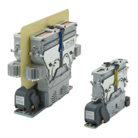
Re-install the auxiliary switch subassembly
After all switches have been replaced and the frame has
been adjusted to a rectangular position, the subassem-
bly can be carefully re-inserted into its original mount-
ing position. Make sure to mount it in the correct same
position as it was before.
Depending on the contactor type, see Fig. 79 to Fig. 82.
X
Insert the entire subassembly (3).
3
Fig. 79: CT/CU 1115/04, 1130/04, 1115/08, 1130/08,
1115/10/11, 1130/10/11: Re-install the auxiliary
switch assembly 1
3
Fig. 80: CT/CU 1215/04, 1230/04, 1215/08, 1230/08,
1215/10/11, 1230/10/11: Re-install the auxiliary
switch assembly 1
X
Screw in the 2 hexagon socket head screws (2) and
tighten the screws with a torque of 2 Nm.
X
Screw in the 2 knurled thumb screws (1) including
washers.
- Tighten the knurled thumb screws (1) by turn-
ing them just once.
X
Check that all replaced parts are properly in place
and xed tightly.
2
1
2
1
Fig. 81: CT/CU 1115/04, 1130/04, 1115/08, 1130/08,
1115/10/11, 1130/10/11: Re-install the auxiliary
switch assembly 2
 Loading...