Do you have a question about the Schaltbau M1 Series and is the answer not in the manual?
Legal restrictions on reproduction and liability for damage.
Symbols used to highlight safety instructions and other important information.
Staff must read, understand, and adhere to instructions and safety warnings.
National instructions, safety regulations, accident prevention, and environmental regulations must be observed.
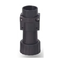
Connectors are for plugin and detachable connections of components, devices, and systems.
Connectors are constructed for specific ambient conditions and temperature ranges.
Hazards related to components carrying voltage and potential for deadly electric shock.
Risks from wrong application, improper use, and electric arcs during plugging/unplugging.
Procedures to prevent connector breakage, cracks, and deformation due to improper handling.
Steps to prevent malfunctions caused by damage, wear, tear, or soiling of connector components.
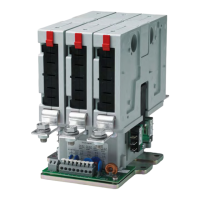
Describes common and special features of M1 and M3 series connectors, including modular design and contact types.
Overview of different connector components for M1 and M3 series and how they can be combined.
Detailed survey of components for M1 and M3 plugs, including cable glands, shell parts, contacts, inserts, and protection caps.
Instructions to check all parts for transport damage before installation.
Procedures for preparing mounting holes and fastening receptacles/plugs with flange or thread.
Lists and describes required tools for insertion, extraction, and crimping of contacts and filler plugs.
Details contact types, models, identifiers, ordering codes, and connection cross-sections.
Explains the structure of the ordering code for contacts, including contact type, diameter, and surface.
Illustrates examples of how connector parts are threaded onto cables for plugs/receptacles.
Instructions on how to make crimp connections according to DIN EN 60352-2, including contact assembly.
Steps for assembling contacts into contact inserts and disassembling them using extraction tools.
Instructions on inserting filler plugs into uncon figured contact cavities of contact inserts.
Procedures for inserting contact inserts into receptacle/plug shells and their coding.
Steps for the final assembly of cable plugs/receptacles with back shells and strain relief.
Steps for plugging connectors, ensuring grooves and guideways interlock correctly.
Steps for unplugging connectors and checking the gap between union nut and shell.
Instructions on how to attach protection caps to plugs and receptacles to prevent dirt ingress.
Defines the intervals for visual and functional checks of connector components.
Outlines the elements to check visually and functionally during every plugging procedure.
Lists extraction tools, insertion tools for socket/pin inserts, and their ordering codes.
Lists spare parts, specifically plastic clips, and their ordering codes.
| Brand | Schaltbau |
|---|---|
| Model | M1 Series |
| Category | Cables and connectors |
| Language | English |