© Allegion 2014
Printed in U.S.A.
44487072 Rev. 01/14-b
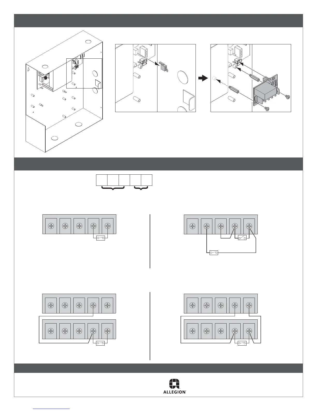
1 b If installing to PS902 main board
Remove Jumper Install 900-FA Here
Note: Complete power failure shall result in a fail safe operation.
When connected to a fire alarm releasing control unit, total
loss of power for the locking mechanisms shall be configured
for a fail safe operation.
2 900-FA wiring
NC FA2FA1NOC
One 900-FA Board - Automatic Reset
Two 900-FA Boards on one power supply
Automatic Reset
NC FA2FA1NOC
NC FA2FA1NOC
NC FA2FA1NOC
One 900-FA Board - Manual Reset
Two 900-FA Boards on two power supplies
Automatic Reset
NC FA2FA1NOC
NC FA2FA1NOC
Supervision Output
Contacts Shown FA Active (open)
Fire Alarm Input
NC C NO FA1 FA2
Fire Alarm Contact
Closed = no fire
Open = fire
Manual Reset
(Temporarily close to reset)
Fire Alarm Contact
Closed = no fire
Open = fire
Fire Alarm Contact
Closed = no fire
Fire Alarm Contact
Closed = no fire
Note: Use 18 gauge wire for all wiring. Wire
length dependent on physical layout.
NOTE: WHEN INSTALLATION IS COMPLETE, SECURE ENCLOSURE DOOR WITH SCREWS OR KEYLOCK