SCOPE COMMUNICATIONS UK LTD
PAGETEK PRO MK2
Ref: PTPROMK2INSTALLred Page 15 of 27 Issue 1
5.2 System Testing
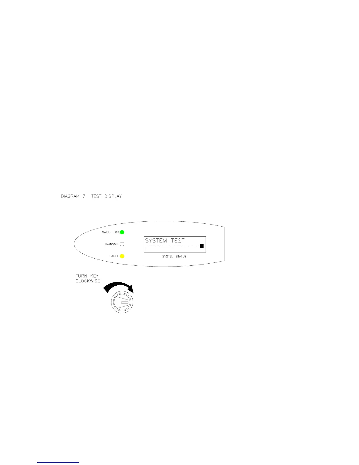
a) To check the functionality of the system and the integrity of the radio link, a key-
operated Test function is provided on the system front panel.
b) Inserting and turning the key a quarter turn clockwise will initiate the Test mode, which
will send one transmission of the message “SYSTEM TEST” to all pagers present on the
system.
c) Whilst in the Test mode, the display will state “SYSTEM TEST” and the yellow fault LED
will be lit. The warning sounder will beep every second as a reminder. See diagram 7.
d) If the system receives a valid Fire trigger whilst in Test mode, the Fire signal will over-
ride the Test message at all times.
e) Always return the key to the ON position before removal. A spare key is also provided.
SYSTEM TESTRESET
ON
Note: whilst in Test mode, the “TX IN SERVICE” transmissions to the pagers are
suppressed. If the system is left in the Test mode for more than two minutes, the
pagers will display “NO SERVICE” until the Test mode is disabled (whereupon the In
Service transmissions will resume). This acts as an additional safety feature to
ensure that the Test condition is switched off after use.
 Loading...